Fluorescent nanoscopy method

a fluorescence nanoscopy and nanoscopy technology, applied in the field of scientific research equipment and lens fluorescence microscopes, can solve the problem of hard to ensure the stability of molecular structures, and achieve the effect of improving the accuracy of the third coordinate definition

Active Publication Date: 2010-09-28
SUPER RESOLUTION TECH
View PDF13 Cites 39 Cited by
  • Summary
  • Abstract
  • Description
  • Claims
  • Application Information

AI Technical Summary

Benefits of technology

[0011]3-D nanoscopy requires total immobility of the object and its parts against an objective lens. That is why the object, after being dyed with caged dye and flushed, should be treated with dehydrating solutions and placed into a polymer non-fluorescent substance (for example, epoxy). Microscopic sections of the object of several microns thickness can be used for 3-D reconstruction of the object with 10-20 nm resolution in all three dimensions. Such an object contained in a solid substance can be lighted as it is done in common fluorescent microscopy. Only an improvement of an additional flash-lamp should be used in order to turn several hundred non-fluorescing molecules into fluorescing in each frame. For both, object in liquid and object in polymer film, a UV flash-lamp with λ<360 nm periodically lights the object, dyed with non-fluorescing dye, and each time turns several hundred (and even a thousand) of non-fluorescing molecules into fluorescing ones by photolysis of special chemical groups blocking fluorescence. The laser constantly lights the object and excites fluorescence of newly formed fluorescent molecules with such strength, that each of them will send several tens of thousands of light quanta in part of a second. Molecules will photobleach after registration of its fluorescence on a digitized frame with low background noise level. Cycling of fluorescent molecules generation, their excitation, registration and photobleaching can be repeated tens of thousands of times. Each time new fluorescence molecules will be generated, detected and photobleached. Not converted non-fluorescent molecules will not photobleach because they do not absorb laser light. Tens of thousands of frames can be detected using this method. Hundreds and even thousands of fluorescing molecules can be detected on each frame. It will allow calculation of locations of all tens of millions of fluorescing molecules covering surfaces of all structures, located in a field of vision. Dyes with different active groups can be used for dyeing structures of different nature in different colors. Active groups can link to either proteins, either nucleic acids, either fats, etc. (one suggested method name is color nanoscopy).
[0014]It should be noted that some parameters of fluorescing particles images, a diameter of spots and light intensity distribution along a section of each spot, can change as particle distances from a focal plane of a microscope object lens. That is why it is suggested to perform a calculation of these parameters in order to calculate a third coordinate of the shining particle. It is suggested to project an object image on two video-cameras. This will improve precision of the third coordinate definition. The light rays are divided in two rays after the object lens. Video-cameras are located so that two neighboring focal planes of the object would be projected on them through one object lens. Light intensity distribution for each particle will be different when detected by different cameras. It can be scaled depending from the third coordinate and used to create 3-D images of the objects. FIG. 3 shows an illustration of 3-D nanoscopy foundations. A diameter and intensity of spots from fluorescing particles which are projected on CCD, depends from a distance between the particle and the object lens. Two cameras, focused on different focal planes, show one particle with different diameters and a different intensity distribution along diameters. The diagrams in the upper right corner of the figure illustrate differences between diameters and a distribution of intensity along diameters depending from cameras and a fluorescing particles location.
[0015]A nanoscope in some cases can be helpful in finding centers of spots which are created by fluorescing particles in two-three different wavelengths and same exciting status. It can be done by separating light dichroic mirrors that pass light with one wavelength to one camera and reflect light with the other wavelength to the other camera. Thus, this invention allows to reconstruct simultaneously with a nano resolution location of several different types of object molecules. These molecules will be dyed with dyes having different emitting wavelengths which will allow enlarged quantities of simultaneously seen and detected separately spots from fluorescing particles. This can be achieved because they can be seen separately in waves of different lengths, even if corresponding spots of different colors are seen interfering.

Problems solved by technology

It is very hard to assure stability of molecular structures for a long time far from covering a glass and a prism glass holding the object.

Method used


Image

  • Fluorescent nanoscopy method
  • Fluorescent nanoscopy method
  • Fluorescent nanoscopy method

Examples


Embodiment Construction

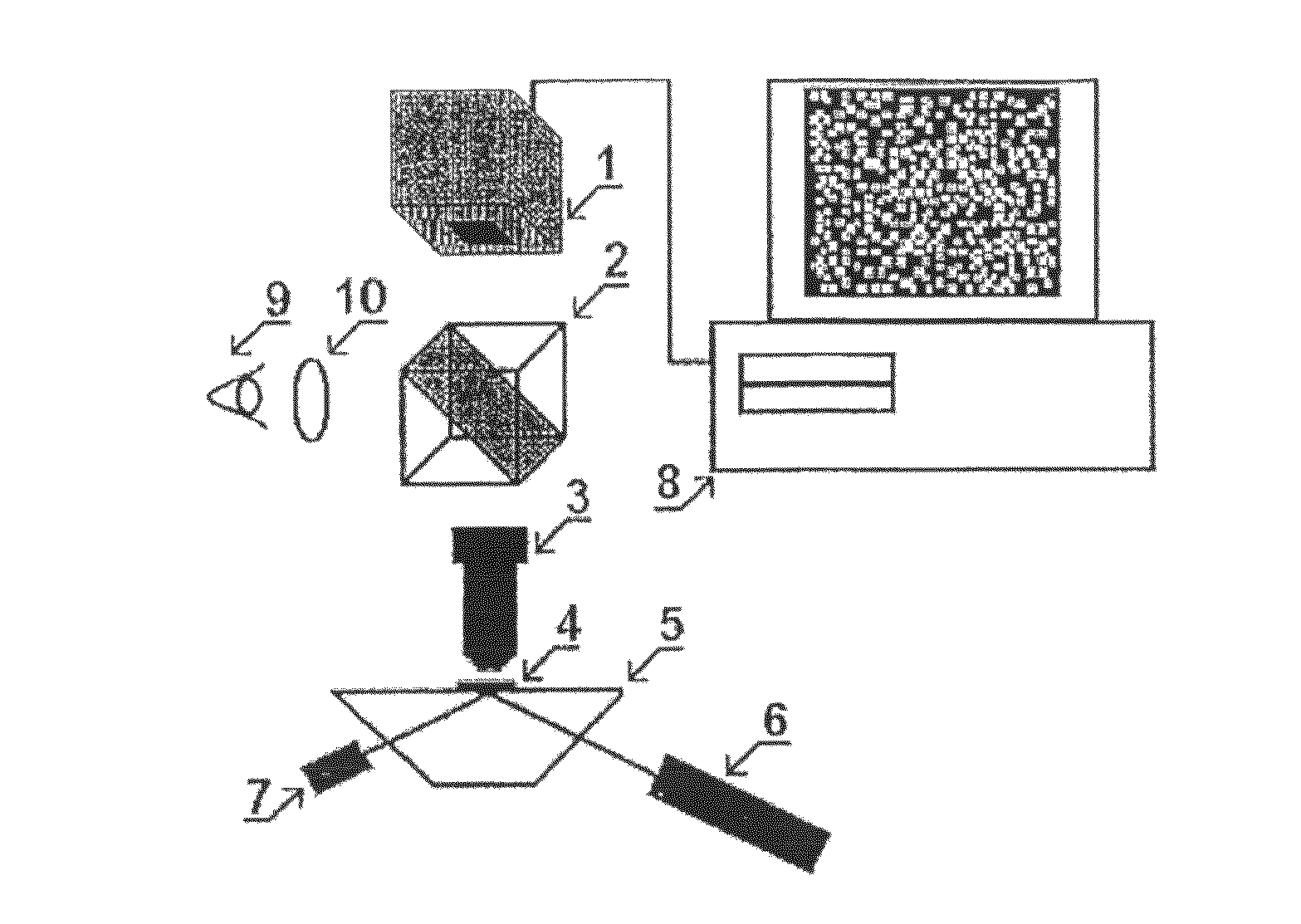
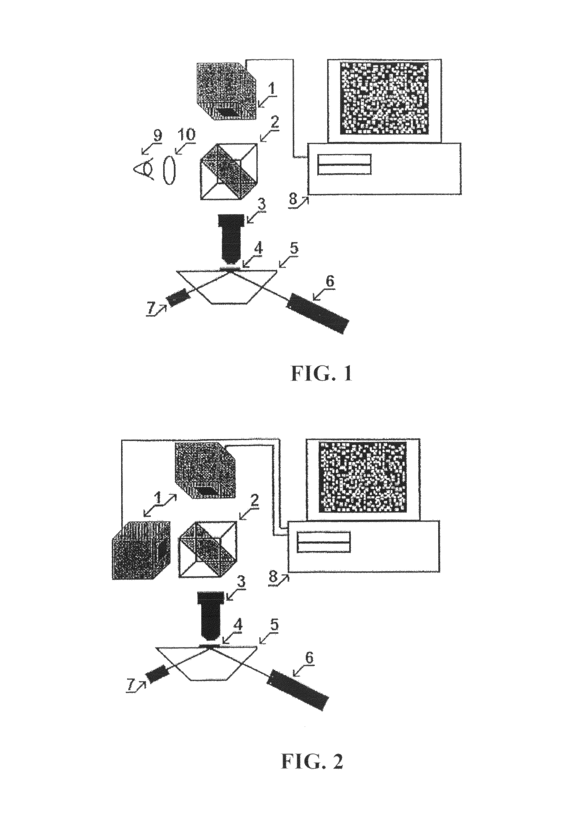
[0020]The fluorescent microscope-nanoscope, as it is shown on FIGS. 1 and 2, is equipped with: one (FIG. 1) and two (FIG. 2) monochrome video-cameras (1) with digital output and suppressing color-filters, located opposite to their sensors (CCD). These color-filters pass only fluorescent light to cameras. A microscope is also equipped with a light dividing removable prism (2); object lens (3) with zoom up to 100× and an aperture up to A=1.4. Object (4) is pressed down to glass object holder (5) which is beveled in the form of truncated prism edges. The device also has laser (6) with lens system for exciting fluorescence through prism planes; with a pulse UV-source with a lens system for photolysis of blocking fluorescence groups, present on dye molecules. Another important part is computer (8) with software for recording and working with digitized images. This software is also used for control of a power source, and providing energy for UV pulses and electrophoresis device. Eye lens ...


PUM

PropertyMeasurementUnit
thicknessaaaaaaaaaa
diameteraaaaaaaaaa
distanceaaaaaaaaaa

Abstract

An analysis of an object dyed with fluorescent coloring agents carried out with the aid of a fluorescent microscope which is modified for improved resolving power and called a nanoscope. The method is carried out with a microscope having an optical system for visualizing and projecting a sample image to a video camera which records and digitizes images of individual fluorescence molecules and nanoparticles at a low noise, a computer for recording and processing images, a sample holder arranged in front of an object lens, a fluorescent radiation exciting source and a set of replaceable suppression filters for separating the sample fluorescent light. Separately fluorescing visible molecules and nanoparticles are periodically formed in different object parts, the laser produces the oscillation thereof which is sufficient for recording the non-overlapping images of the molecules and nanoparticles and for decoloring already recorded fluorescent molecules, wherein tens of thousands of pictures of recorded individual molecule and nanoparticle images, in the form of stains having a diameter on the order of a fluorescent light wavelength multiplied by a microscope amplification, are processed by a computer for searching the coordinates of the stain centers and building the object image according to millions of calculated stain center co-ordinates corresponding to the co-ordinates of the individual fluorescent molecules and nanoparticles. With this invention it is possible to obtain a two-dimensional and a three-dimensional image with a resolving power better than 20 nm and to record a color image by dyeing proteins, nucleic acids and lipids with different coloring agents.

Description

BACKGROUND OF THE INVENTION[0001]1. Field of the Invention[0002]This invention relates to equipment for scientific research, and lens fluorescence microscopes in particular, that are used for obtaining images of fluorescent objects immobilized on a glass. This invention also relates to a computerized fluorescent-microscopically method of reconstructing images of objects with resolution up to several nanometers (nm).[0003]2. Discussion of Related Art[0004]There are known optical microscopes which can create zoomed images of an object with object lenses that can show two spots on an object separately only when the distance between them is more than so called diffraction limit. This limit can be calculated using following formula: r=0.61λ / A (1), where λ is light wavelength for light collected by object lens with aperture A=n*sin(φ), n is a refraction index of substance which surrounds object spots, φ is an angle between object lens axis and extreme rays which fall into object lens and ...

Claims


Application Information

Patent Timeline
Patent Type & Authority Patents(United States)
IPC IPC(8): G01N21/76G01N1/00
CPCG01N21/6458G01N21/6486H04N7/18H04N13/0275G01N21/6428Y10S977/84Y10T436/143333Y10S977/881Y10S977/868Y10T436/25Y10S977/869H04N13/275
Inventor KLIMOV, ANDREY ALEXEEVICHKLIMOV, DMITRY ANDREEVICHKLIMOV, EVGENIY ANDREEVICHKLIMOVA, TATIANA VITALYEVNA
Owner SUPER RESOLUTION TECH
Why Eureka
Try Eureka