Integrated coal gasification combined cycle plant

a gasification combined cycle and integrated technology, applied in the direction of machines/engines, emission prevention, lighting and heating apparatus, etc., can solve the problems of reduced output of steam turbines which utilize steam generated by corrosion problems, and reduced thermal energy of gas turbine exhaust gas at heat recovery steam generators, etc., to achieve high efficiency

Inactive Publication Date: 2010-10-19
MITSUBISHI HEAVY IND LTD
View PDF31 Cites 6 Cited by
  • Summary
  • Abstract
  • Description
  • Claims
  • Application Information

AI Technical Summary

Benefits of technology

[0009]The present invention has been conceived in view of the above situation, and an object of the present invention is to provide an integrated coal gasification combined cycle plant in which, when, the gas temperature at the, outlet of a heat recovery steam generator is set to a value equal to or lower than the dew point of sulfuric acid, the corrosion problem of a heat exchanger can be solved and high efficiency can be realized.
[0013]In this case, the acid-resistant feedwater heater is preferably disposed at an area where the temperature of the combustion exhaust gas is lower than the dew point of sulfuric acid. Consequently, thermal energy possessed by the combustion exhaust gas can be effectively utilized while minimizing the use of the expensive acid-resistant feedwater heater.
[0016]According to the above integrated coal gasification combined cycle plant of the present invention, the heat recovery steam generator includes the acid-resistant feedwater heater for preheating the boiler feedwater at the downstream side thereof. Therefore, steam can be generated by maximally utilizing thermal energy possessed by the combustion exhaust gas without being concerned with the corrosion problem of a heat exchanger caused by sulfuric acid produced from a sulfur component contained in the combustion exhaust gas. Consequently, significant advantages can be achieved, namely, realizing an integrated coal gasification combined cycle plant with high efficiency and improving the durability of the plant. In particular, when the acid-resistant feedwater heater is disposed at an area where the temperature of the combustion exhaust gas is lower than the dew point of sulfuric acid, and preheating of the boiler feedwater is performed, an integrated coal gasification combined cycle plant with high efficiency can be realized at low cost.
[0017]Furthermore, when the cleaning water spray device is provided at the upstream side of the acid-resistant feedwater heater, the cleaning fluid can be sprayed in the same direction as the flow direction of the combustion exhaust gas. Consequently, the acid-resistant feedwater heater and some equipments disposed at the downstream side thereof etc. can be cleaned without stopping the operation of the power generation plant.

Problems solved by technology

However, since a heat recovery steam generator (HRSG) provided at the downstream side of the gas turbine includes a carbon steel heat exchanger therein, sulfuric acid produced from the sulfur component causes a corrosion problem.
However, when the gas temperature at the outlet of the heat recovery steam generator is set at a high value, thermal energy of a gas recovered from the exhaust gas of the gas turbine at the heat recovery steam generator is decreased.
Consequently, the output of a steam turbine which utilizes steam generated by heat recovery steam generator is decreased, thereby decreasing the plant efficiency.
Consequently, the amount of heat recovery is decreased, resulting in a problem of reduced power generation efficiency (see, for example, Japanese Unexamined Patent Application, Publication No.

Method used


Image

  • Integrated coal gasification combined cycle plant
  • Integrated coal gasification combined cycle plant
  • Integrated coal gasification combined cycle plant

Examples


Embodiment Construction

[0020]An embodiment of an integrated coal gasification combined cycle plant according to the present invention will now be described with reference to the drawings.

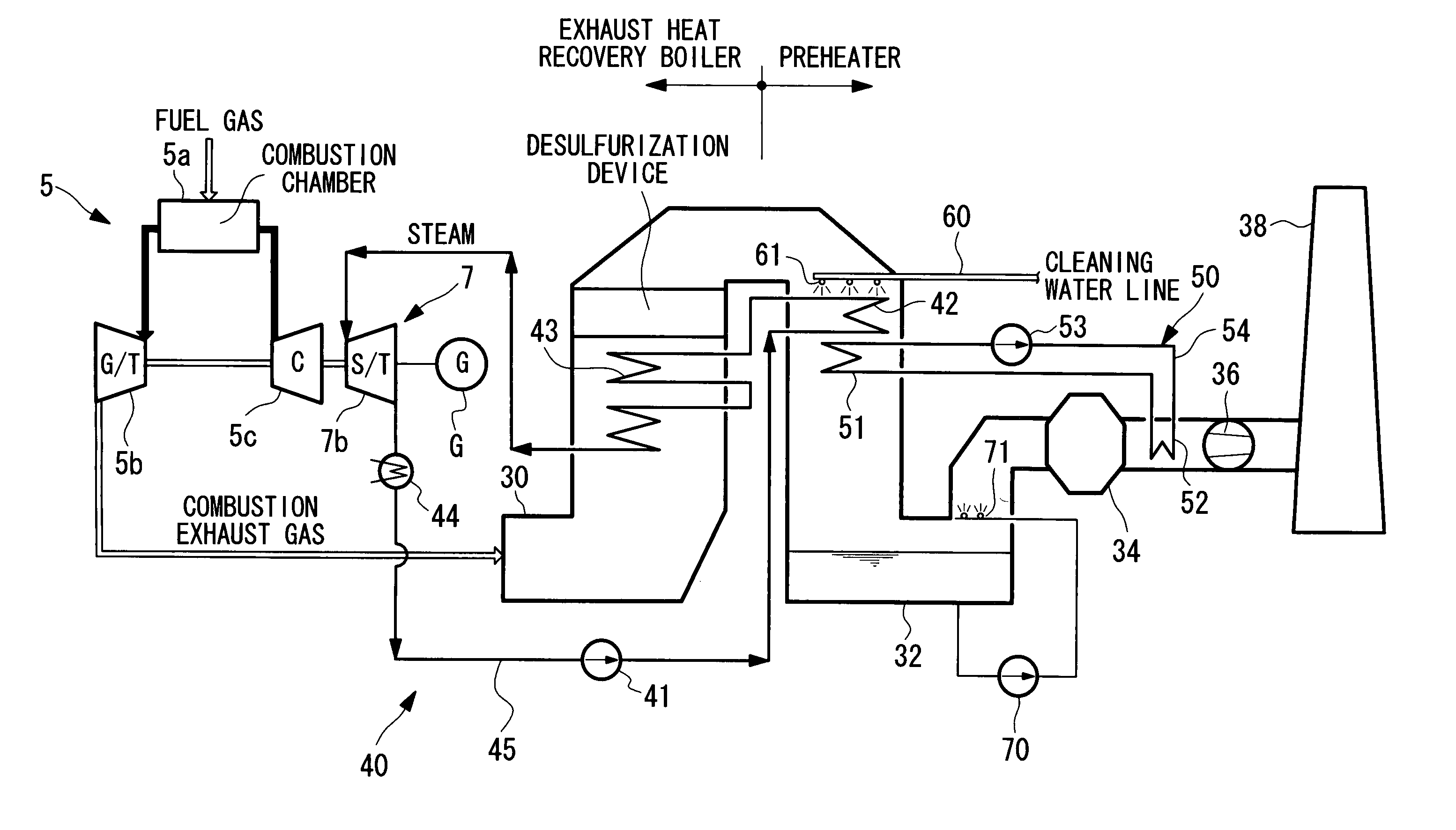
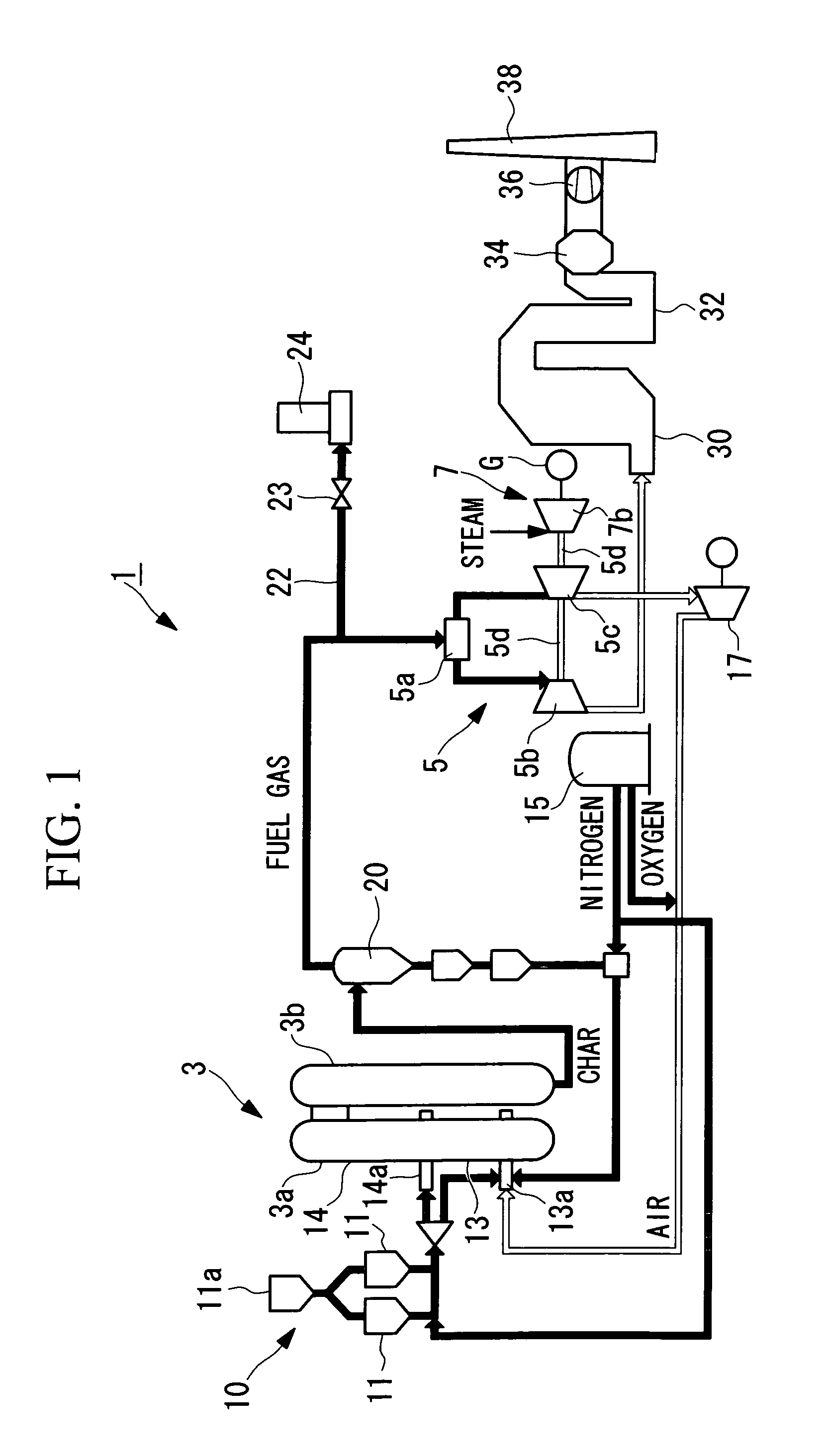
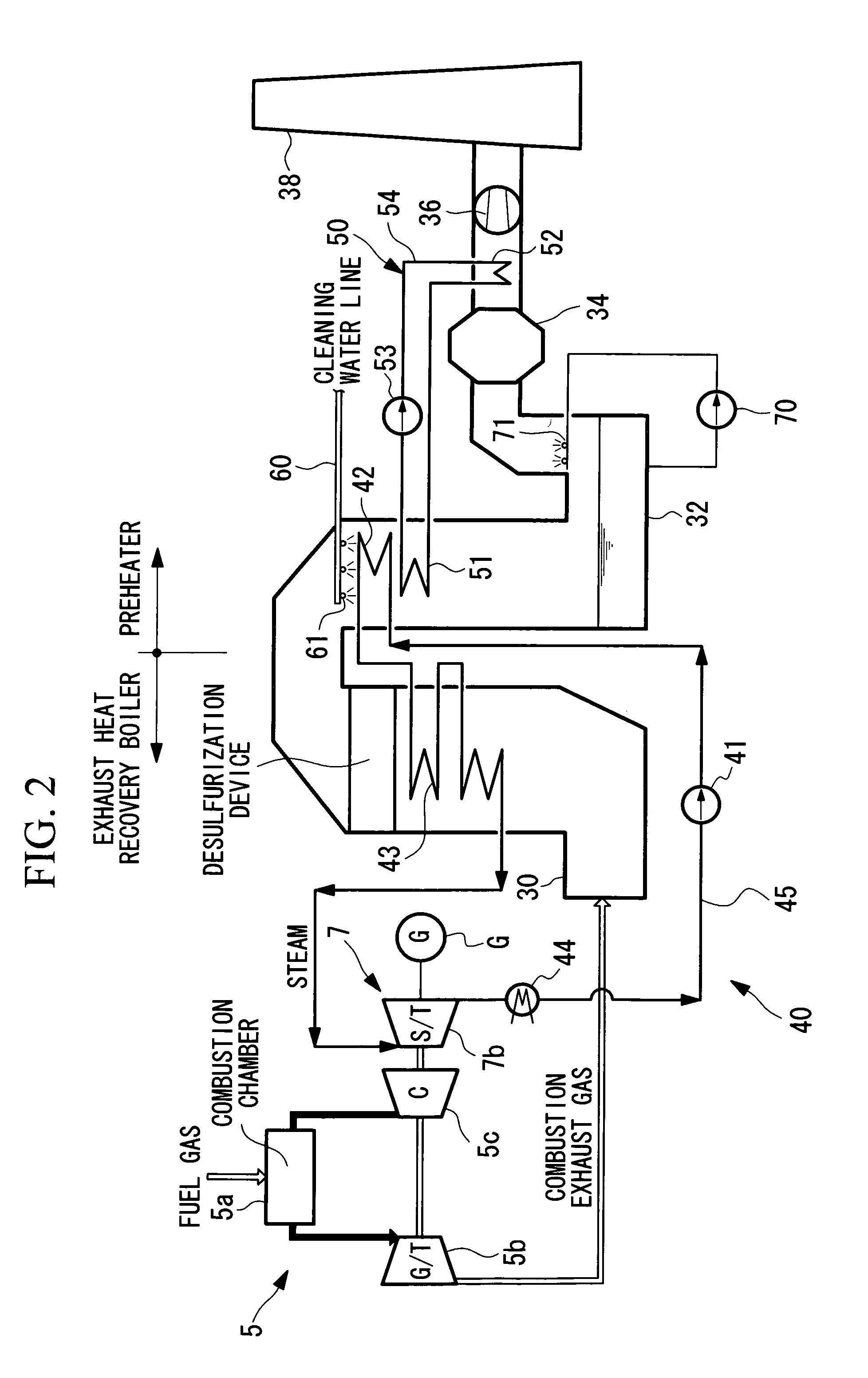
[0021]As shown in FIG. 1, an integrated coal gasification combined cycle (hereinafter referred to as “IGCC”) plant 1, using coal as fuel, primarily includes a gasifier 3, a gas turbine 5, and a steam turbine 7.

[0022]A coal supply system 10 for supplying pulverized coal to the gasifier 3 is provided at an upstream side thereof. This coal supply system 10 has a pulverizer (not shown) which pulverizes raw coal into pulverized coal having a particle size of several to several hundreds of micrometers and is designed so that the pulverized coal is stored in the pulverized coal bin 11a.

[0023]The pulverized coal stored in the bin 11a is fed at a constant flow rate to the gasifier 3 together with nitrogen gas supplied from an air separation unit 15.

[0024]The gasifier 3 has a coal gasification section 3a which is designed so that ...


PUM


Abstract

The problem of a heat exchanger of a heat recovery steam generator being corroded by sulfuric acid is solved, and the gas temperature at the outlet of the heat recovery steam generator is set at a value equal to or lower than the dew point of sulfuric acid, thereby realizing an integrated coal gasification combined cycle plant with high efficiency. A flue-gas-desulfurization-type integrated coal gasification combined cycle plant includes a gasifier configured to convert pulverized coal to a gas fuel; an heat recovery steam generator configured to generate steam; a gas turbine which is operated by the gas fuel and which supplies a combustion exhaust gas to the heat recovery steam generator; a steam turbine which is operated by the steam generated by the heat recovery steam generator; a power generator connected to at least one of the gas turbine and the steam turbine; and a desulfurization equipment configured to desulfurize the combustion exhaust gas discharged from the heat recovery steam generator, the desulfurized combustion exhaust gas being exhausted into the atmosphere, wherein the heat recovery steam generator includes an acid-resistant feedwater heater which preheats boiler feedwater and which is provided at the downstream side of a main heat exchanger.

Description

BACKGROUND OF THE INVENTION[0001]1. Field of the Invention[0002]The present invention relates to an integrated coal gasification combined cycle plant for combined power generation using coal as fuel, and in particular, to an increase in the plant efficiency in a flue-gas-desulfurization-type integrated coal gasification combined cycle plant.[0003]This application is based on Japanese Patent Application No. 2004-188886, the content of which is incorporated herein by reference.[0004]2. Description of Related Art[0005]Heretofore, a flue-gas-desulfurization-type integrated coal gasification combined cycle (hereinafter referred to as “IGCC”) plant has been known. In such a flue-gas-desulfurization-type IGCC plant, an exhaust gas in a gas turbine contains a large amount of a sulfur component. However, since a heat recovery steam generator (HRSG) provided at the downstream side of the gas turbine includes a carbon steel heat exchanger therein, sulfuric acid produced from the sulfur compone...

Claims


Application Information

Patent Timeline
Patent Type & Authority Patents(United States)
IPC IPC(8): F02C3/26
CPCF01K23/068F01K23/16F23J15/025F23J15/04F23J15/08F23J2215/20F23J2217/102F23J2219/40F23J2219/70F23J2219/80Y02E20/18Y02E20/16
Inventor YOSHIDA, NAOSHIGE
Owner MITSUBISHI HEAVY IND LTD
Why Eureka
Try Eureka