
Intelligent memory device clock distribution architecture

a clock distribution and memory device technology, applied in the field of computer design and computer architecture, can solve problems such as memory latency, compiler complexity, multi-processor coordination, etc., and achieve the effect of extraordinary capability

Inactive Publication Date: 2010-10-26
KLINGMAN REVOCABLE TRUST
View PDF31 Cites 0 Cited by
  • Summary
  • Abstract
  • Description
  • Claims
  • Application Information

AI Technical Summary

Benefits of technology

"The patent describes an architecture for a computer system that can execute tasks efficiently. The system uses a Scheduler unit to select tasks and a Dataflow unit to transfer data to the system's Processing Elements (PE). The PE performs the necessary operations and transfers the results back to the Scheduler unit. The Scheduler unit updates the task state and advances to the next task. The system can adapt to different task code and data types and sizes. The preferred encoding scheme is ASCII, which allows for efficient task execution and data transfer. The system can manage multiple tasks simultaneously and has a large register set for task data. The technical effects of the system include improved performance and flexibility for different applications."

Problems solved by technology

The three major problems facing computer designers today involve (i) memory latency; (ii) multi-processor co-ordination; and (iii) compiler complexity.
However, a dichotomy exists between random logic gates of a CPU and arrays of logic storage gates in a memory, because each physically evolved in specialized manner, due to different manufacturing optimizations.
Because memory technology and processor / logic manufacturing technology evolved separately, large capacity memories cannot be integrated with high speed processors on one die, so the two have classically been packaged separately and wired together.
The distances and capacitances associated with this wiring involve access delays many times those involved in on-chip access.
A problem with this approach is branching wherein the pipeline must be flushed and refilled at the branch target location.
Very large operating systems (OSs) try to run code from the same base address, causing aliasing problems in caches and flushes.
In general, processor performance is limited by memory latency.
Nevertheless, memory latencies will never be zero and the problem will not be completely solved via faster memory.
However, due to the separate evolutionary paths taken by CPU and memory manufacturing technologies, this is unlikely to occur soon.
Although, in theory, many different sizes could be manufactured, the multi-million dollar, exponentially increasing costs of masks argues against this, even if the technology were feasible.
SOC-relevant measures of optimality tend to be power consumption, not high speed, so this does not solve the general purpose CPU problem, which is based on the fact that CPU address space can always exceed on-chip memory capacity.
MIPS implies this is true by arguing that DSP hardware coprocessors are used, not because CPU instructions cannot perform the computations, but because single thread CPUs, even with real time OS, cannot guarantee hard real-time deadlines.
This closely coupled mechanism is appropriate to a CPU executing a Java program, and very little else, since a polling processor is doing no useful work.

Method used


Image

  • Intelligent memory device clock distribution architecture
  • Intelligent memory device clock distribution architecture
  • Intelligent memory device clock distribution architecture

Examples


Embodiment Construction

The iMEM Structure

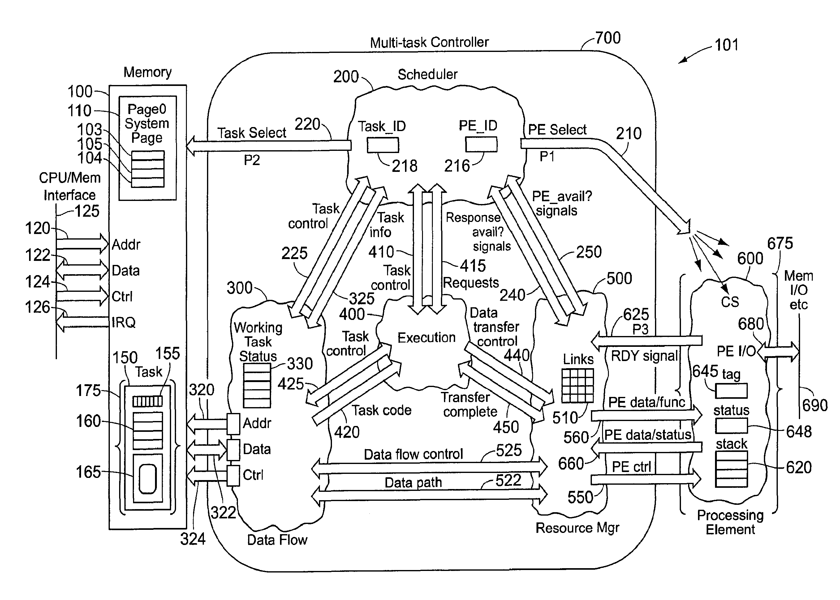
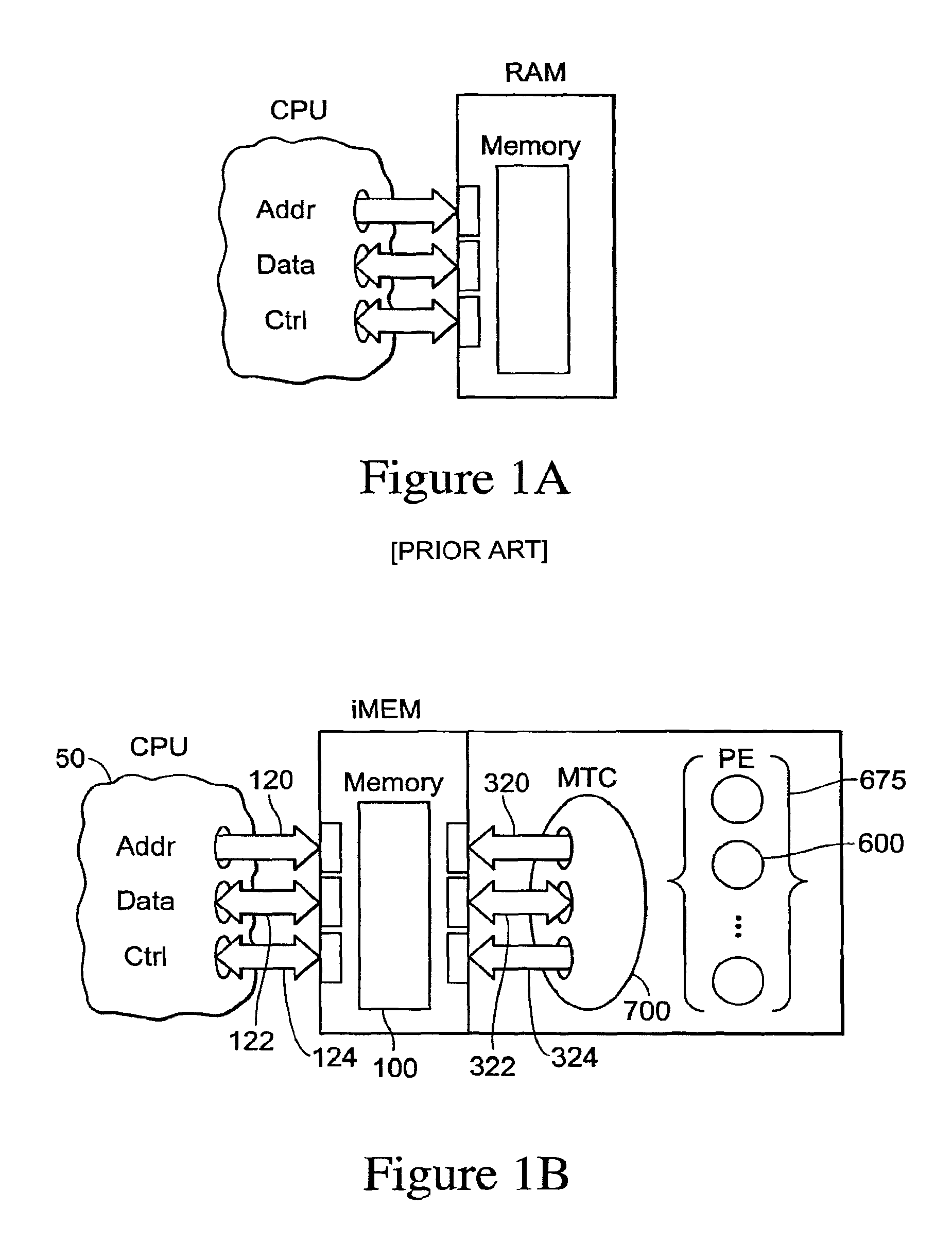
[0080]Common to all of the above attempts to solve the memory latency problem, except Cybernetic's and Micron's, is maintenance of the CPU-memory dichotomy, i.e., all of the intelligence is positioned in the processor, none in the memory. The invention described herein alters this architecture as shown in FIG. 1B. The processor characteristics include (i) autonomous processing; (ii) local memory space(s) access; and (iii) I / O channels. The memory characteristics include (i) an address bus; (ii) a data bus; and (iii) a control bus (Read, Write, Enable, Ready, etc.). The intelligent memory characteristics include: (i) an address bus; (ii) a data bus; (iii) a control bus; (iv) processing disabled by default; (v) processing enabled via the memory interface; and (vi) optional I / O channels.

[0081]The iMEM device looks like classical memory to the CPU 50 and responds as such to the CPU address 120, control 124, and data busses 122. Within the iMEM, however, exists consider...


PUM


Abstract

A computing system that includes one or more processing elements, a memory connected to a host processor and a multitask controller, where the multitask controller includes a scheduler unit, a data flow unit, an executive unit, and a resource manager unit. The processing elements, the scheduler unit, the data flow unit, the executive unit, and the resource manager unit are each synchronously clocked by a clock signal. The processing elements, multitask controller interface of the memory, the executive unit, and the scheduler unit are each operative to change one or more interface signals on a positive transition of the clock signal while the resource manager unit and dataflow unit are each operative to change one or more interface signals on a negative transition of the clock signal. Because adjacent units are clocked on opposite edges, the speed of transfer of information between the units is improved.

Description

CROSS-REFERENCE TO RELATED APPLICATIONS[0001]This application claims priority to prior U.S. Provisional Patent Application Ser. No. 60 / 540,671, filed Jan. 29, 2004 and titled “INTELLIGENT MEMORY DEVICE ARCHITECTURE,” which application is hereby incorporated by reference into the instant application.[0002]This application is related to U.S. patent application Ser. No. 10 / 831,649, filed Apr. 23, 2004 and titled INTELLIGENT MEMORY DEVICE, now U.S. Pat. No. 7,594,232, which application is hereby incorporated by reference into the instant application.[0003]This application is related to U.S. patent application Ser. No. 10 / 938,990, filed on Sep. 9, 2004 now abandoned and titled “INTELLIGENT MEMORY DEVICE WITH ASCII REGISTERS,” which application is hereby incorporated by reference into the instant application.[0004]This application is related to U.S. patent application Ser. No. 10 / 957,431, filed on Sep. 30, 2004 and titled “INTELLIGENT MEMORY DEVICE WITH WAKEUP FEATURE,” which application ...

Claims


Application Information

Patent Timeline
Patent Type & Authority Patents(United States)
IPC IPC(8): G06F3/00G06F12/00G11C5/00
CPCG06F9/4825G06F9/5038G06F9/5066G06F9/52G06F9/544
Inventor KLINGMAN, EDWIN E.
Owner KLINGMAN REVOCABLE TRUST
Learn More