
High-speed receiver architecture

a receiver and high-speed technology, applied in the field of high-speed data communication, can solve the problems of difficult and expensive to build with the required resolution, many challenges to implement 10 g systems, and various other components in the receiver may also be difficult or expensive to build at this speed of operation

Active Publication Date: 2010-12-14
MARVELL ASIA PTE LTD
View PDF29 Cites 19 Cited by
  • Summary
  • Abstract
  • Description
  • Claims
  • Application Information

AI Technical Summary

Benefits of technology

The present invention provides a receiver and / or transceiver with various features and combinations of features. The receiver includes an interleaved ADC with a multi-channel equalizer that can compensate for channel-dependent impairments. The equalizer can be a feedforward equalizer or a Viterbi decoder with an FFE. The interleaved ADC can use open-loop residue amplifiers or calibration to correct non-linearity. The equalizer can be calibrated using the LMS algorithm. The multi-channel equalizer can include different combinations of features such as N-tap, M-parallel FIR filters, and shared coefficients. The equalizer can be adapted on a sub-sampled basis. The timing recovery circuit can adapt to time-varying impulse responses. The automatic gain control can be applied to the incoming signal. The chip includes a programmable gain amplifier and a multi-stage gain control. The multi-channel equalizer can be implemented with a factor of two demultiplexing and can include a lookup table-based architecture. The invention provides a more efficient and effective solution for equalization in high-speed receivers and transceivers.

Problems solved by technology

However, there are many challenges to implementing 10 G systems, especially over multi-mode fibers.
However, a 10 G system requires a 10 G ADC, which can be difficult and expensive to build with the required resolution.
More generally, various other components in the receiver may also be difficult or expensive to build at this speed of operation.
However, added complexity often comes at the price of higher cost or lower reliability.
The use of different materials systems may increase the cost by increasing the overall count of integrated circuits if the materials systems cannot be combined on a single integrated circuit.

Method used


Image

  • High-speed receiver architecture
  • High-speed receiver architecture
  • High-speed receiver architecture

Examples


Embodiment Construction

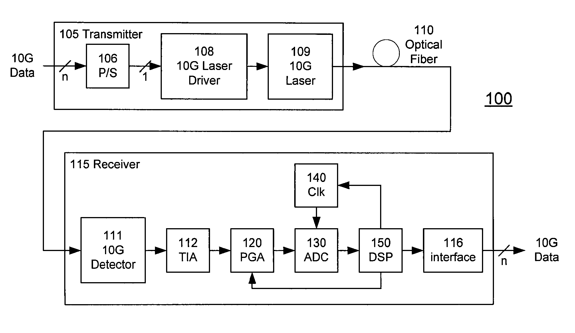
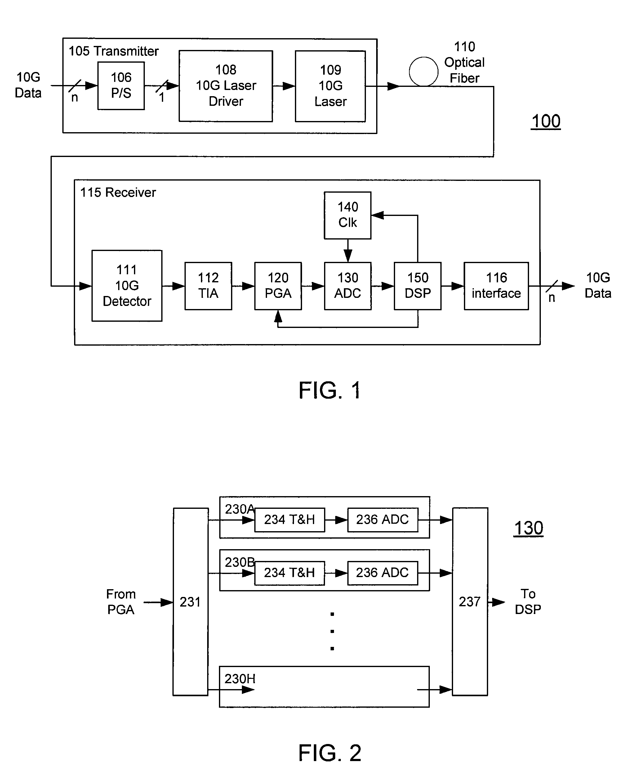
[0041]FIG. 1 shows an optical fiber communications link 100 according to the invention. The link 100 includes a transmitter 105 coupled through optical fiber 110 (the communications channel) to a receiver 115. A typical transmitter 105 may include a serializer or parallel / serial converter (P / S) 106 for receiving data from a data source on a plurality of parallel lines and providing serial data to a laser driver 108. The driver 108 then drives a laser source 109, for example a 1310 nm Fabry-Perot or DFB laser. The laser source 109 launches the optical waveform carrying the digital data on optical fiber 110.

[0042]On the receive side, a typical receiver 115 includes a photodetector 111 for receiving and detecting data from the optical fiber 110. The detected data is typically processed through a transimpedance amplifier (TIA) 112. A programmable gain amplifier (PGA) 120 applies a variable gain to the electrical analog signal. The resulting electrical signal is converted to digital form...


PUM


Abstract

A receiver (e.g., for a 10 G fiber communications link) includes an interleaved ADC coupled to a multi-channel equalizer that can provide different equalization for different ADC channels within the interleaved ADC. That is, the multi-channel equalizer can compensate for channel-dependent impairments. In one approach, the multi-channel equalizer is a feedforward equalizer (FFE) coupled to a Viterbi decoder, for example a sliding block Viterbi decoder (SBVD); and the FFE and / or the channel estimator for the Viterbi decoder are adapted using the LMS algorithm.

Description

CROSS-REFERENCE TO RELATED APPLICATION(S)[0001]This application (a) claims priority under 35 U.S.C. §119(e) to U.S. Provisional Patent Application Ser. No. 60 / 737,103, “EDC Transceiver: System and Chip Architecture,” filed Nov. 15, 2005 by Oscar E. Agazzi et al.; (b) claims priority under 35 U.S.C. §119(e) to U.S. Provisional Patent Application Ser. Nos. 60 / 779,200, “MIMO / MLSE Receiver for Electronic Dispersion Compensation of Multimode Optical Fibers,” filed Mar. 3, 2006 by Oscar E. Agazzi et al. and 60 / 783,344, “MIMO / MLSE Receiver for Electronic Dispersion Compensation of Multimode Optical Fibers,” filed Mar. 16, 2006 by Oscar E. Agazzi et al.; (c) is a continuation-in-part of U.S. Utility patent application Ser. No. 11 / 538,025, “Multi-Channel Equalization to Compensate for Impairments Introduced by Interleaved Devices,” filed Oct. 2, 2006 by Oscar E. Agazzi et al.; which claims priority under 35 U.S.C. §119(e) to U.S. Provisional Patent Application Ser. No. 60 / 723,357, “Compensat...

Claims


Application Information

Patent Timeline
Patent Type & Authority Patents(United States)
IPC IPC(8): H03K5/159
CPCH03M1/0626H04B10/6971H04L1/0054H04L1/0071H04L25/0204H04L25/03038H04L25/03057H04L25/03184H04L25/03292H03M1/1215H04L1/06H04L25/025H04L2025/03356H04L2025/03426H04L2025/03477H04L2025/03617H03M1/1004H03M1/44
Inventor AGAZZI, OSCAR E.CRIVELLI, DIEGO E.CARRER, HUGO S.HUEDA, MARIO R.LUNA, GERMAN C.GRACE, CARL
Owner MARVELL ASIA PTE LTD
Learn More