
Heteroionic junction light emitting electrochemical cell

a technology of electrochemical cells and heteroionic junctions, applied in the direction of discharge tubes/lamp details, discharge tubes luminescnet screens, conductors, etc., can solve the problems of inconvenient materials, material inability to meet the needs of use, etc., to achieve optimal light emission efficiency

Inactive Publication Date: 2011-03-08
OREGON HEALTH & SCI UNIV
View PDF0 Cites 1 Cited by
  • Summary
  • Abstract
  • Description
  • Claims
  • Application Information

AI Technical Summary

Benefits of technology

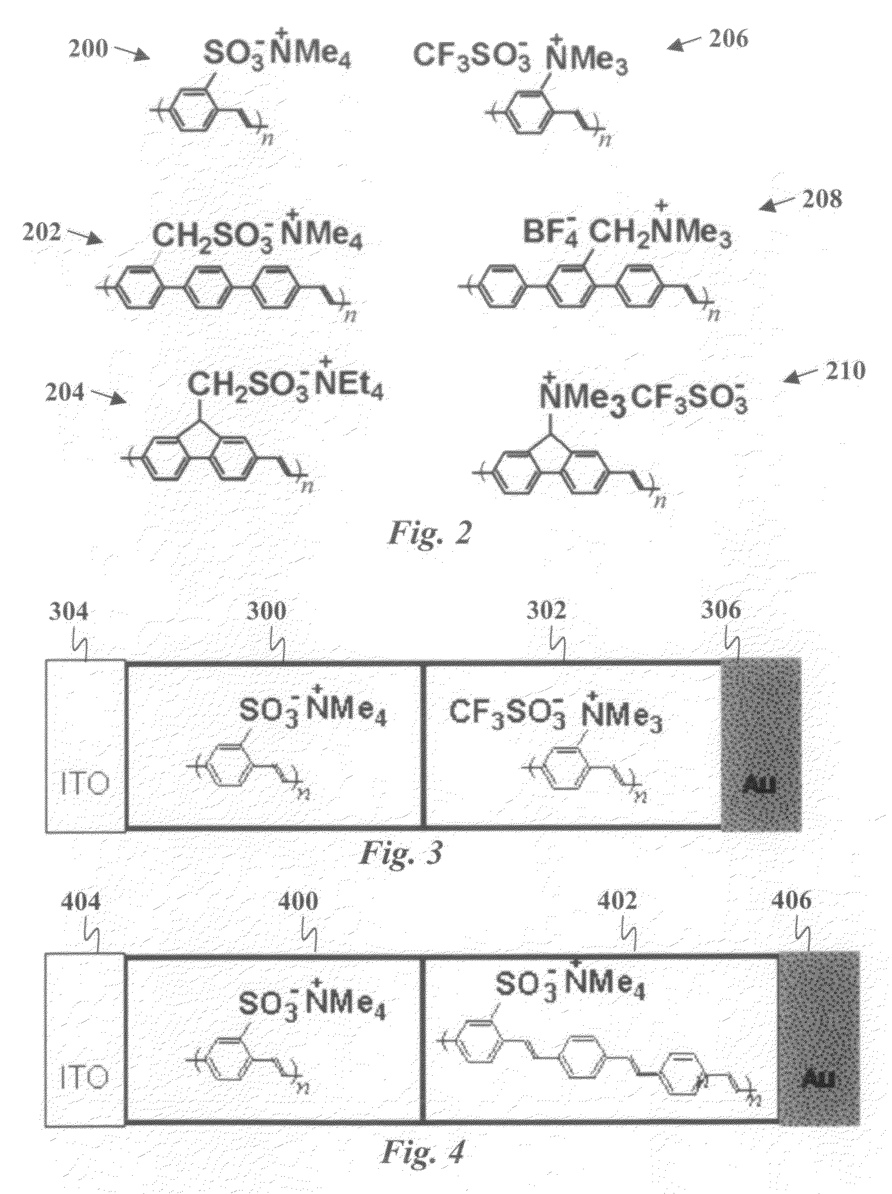
The present invention is about materials and structures for PLEC devices that provide high efficiency and stability through precise balancing electron and hole injection. The devices use a heteroionic junction composed of two layers of conjugated ionomers with differing ion content to control the potential between the anode and cathode, thereby increasing efficiency and decreasing drive voltage. The use of luminescent conjugated ionomers with varied ionic functional group density reduces the susceptibility to degradative over-oxidation or over-reduction of the active polymer. The devices are characterized by optimized electroluminescence with respect to changes in ion concentrations in the active layers. The heteroionic junction structure also provides material stability due to ionic isolation of the two layers from each other.

Problems solved by technology

Current PLEC devices, however, suffer from various limitations including energy inefficiency and instability of the materials due to degradative over-oxidation or over-reduction of the active polymer.
These materials are not suitable because they contain free salt.
Consequently, ambipolar diffusion of neutral anion-cation pairs will destroy any differential in ion content between contacted materials.

Method used


Image

  • Heteroionic junction light emitting electrochemical cell
  • Heteroionic junction light emitting electrochemical cell
  • Heteroionic junction light emitting electrochemical cell

Examples


Embodiment Construction

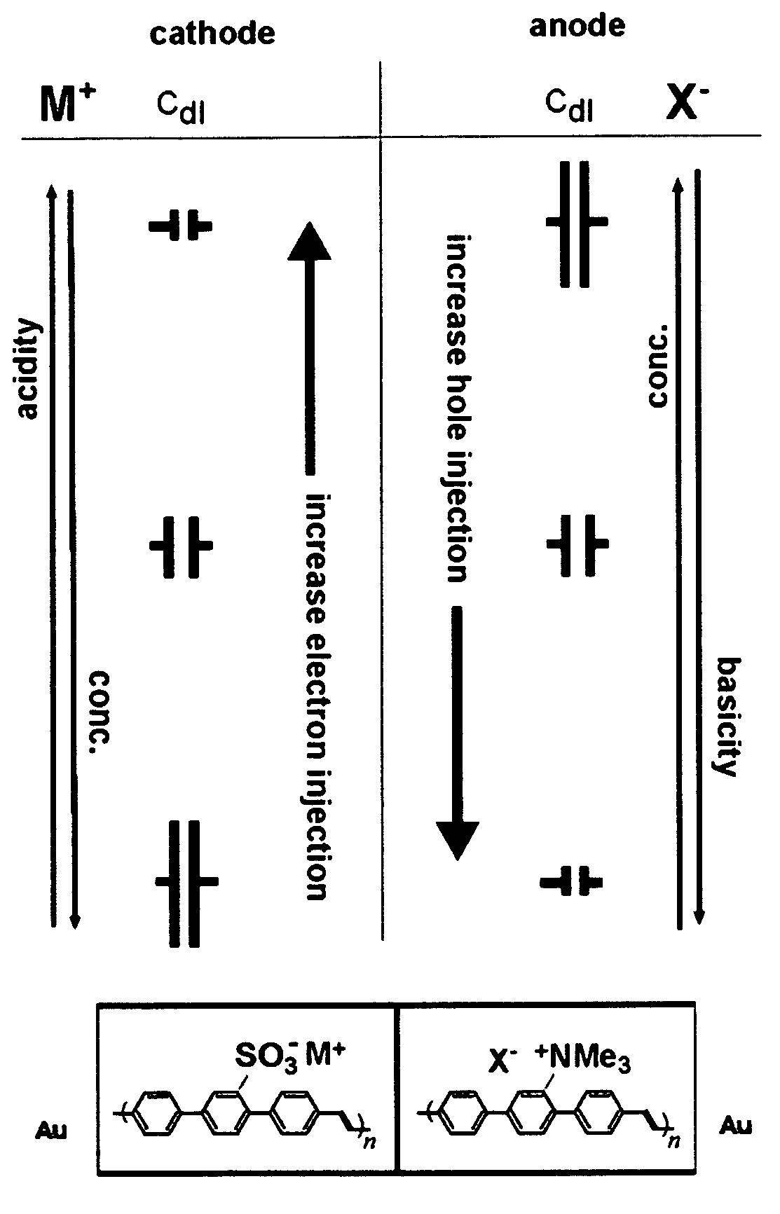
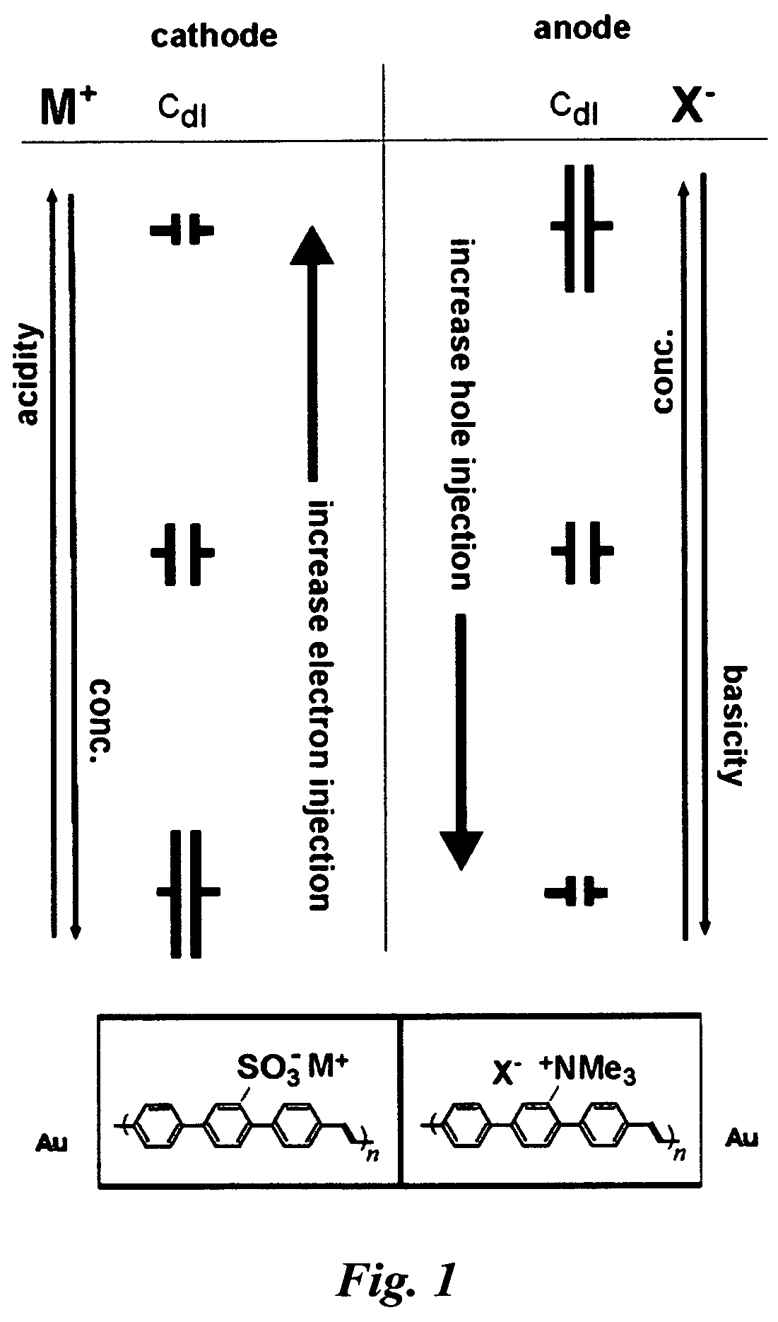
[0022]Embodiments of the present invention are based on a two-layer heteroionic structure designed using principles of double layer capacitance engineering to control of the ion content in the active layers so as to balance electron and hole injection, thereby increasing the efficiency of the device. The concept of double layer capacitance engineering (CdlE) relies on the unique properties of mixed ionic / electronic conductors (MIECs) interfaced to ion blocking electrodes. The capacitance per unit area (Cdl) due to the polarization of ions at a blocking electrode is given, in the zero bias Guoy-Chapman limit, by:

[0023]Cdl=2⁢z2⁢e2⁢ɛ⁢⁢nkB⁢T(1)

where e is the elementary charge, ze is the magnitude of the charge on the ions, n is the free ion concentration, ∈ is the dielectric constant, kB is the Boltzmann constant, and T is the temperature. It is important to note that, in general, Cdl does depend on applied bias.

[0024]The most important aspect of eq. (1) is that Cdl can be tailored thro...


PUM


Abstract

A structure for high performance light emitting electrochemical cells comprises at least two active layers of mixed ionic / electronic conducting materials, at least one of which is electroluminescent. The active layers are sandwiched between ion blocking electrodes, typically metal and / or transparent conducting oxide, that are electrically but not ionically conductive. Application of bias to the electrodes results in the polarization of ions at the electrodes thereby generating a field to drive the injection of electronic carriers into the active layer. The injected electron and holes recombine within the active layers to emit light. The ability to balance electron and hole injection in the design of such devices provides for optimal light emission efficiency.

Description

CROSS-REFERENCE TO RELATED APPLICATIONS[0001]This application is a continuation-in-part of U.S. patent application Ser. No. 11 / 820,861 filed Jun. 20, 2007, now abandoned which claims priority from U.S. provisional patent application No. 60 / 815,542 filed Jun. 20, 2006, both of which are incorporated herein by reference.STATEMENT OF GOVERNMENT SPONSORED SUPPORT[0002]This invention was made with Government support under Grant No. DMR 0210078 awarded by the NSF. The US Government has certain rights in this invention.FIELD OF THE INVENTION[0003]The present invention relates generally to light-emitting devices and materials. More specifically, it relates to improved polymer light emitting electrochemical cells.BACKGROUND OF THE INVENTION[0004]A conventional polymer light-emitting electrochemical cell (PLEC) is composed of a mixture of a luminescent polymer and a polymer salt complex. The mixture is positioned between two electrodes, at least one of which is transparent (e.g., indium tin o...

Claims


Application Information

Patent Timeline
Patent Type & Authority Patents(United States)
IPC IPC(8): H01J1/62H01J63/04
CPCH01B1/122H01L51/5032H10K50/135
Inventor LONERGAN, MARK C.CHENG, CALVIN H. W.JOHNSTON, DEAN H.
Owner OREGON HEALTH & SCI UNIV
Learn More