
Methods and apparatus for swept-source optical coherence tomography

a technology of optical coherence tomography and optical coherence, applied in the field of optical imaging, can solve the problems of limited scan range, phase jitter, poor noise performance, etc., and achieve the effects of low noise, stable, efficient operation, and high speed

Active Publication Date: 2011-03-29
LIGHTLAB IMAGING
View PDF38 Cites 150 Cited by
  • Summary
  • Abstract
  • Description
  • Claims
  • Application Information

AI Technical Summary

Benefits of technology

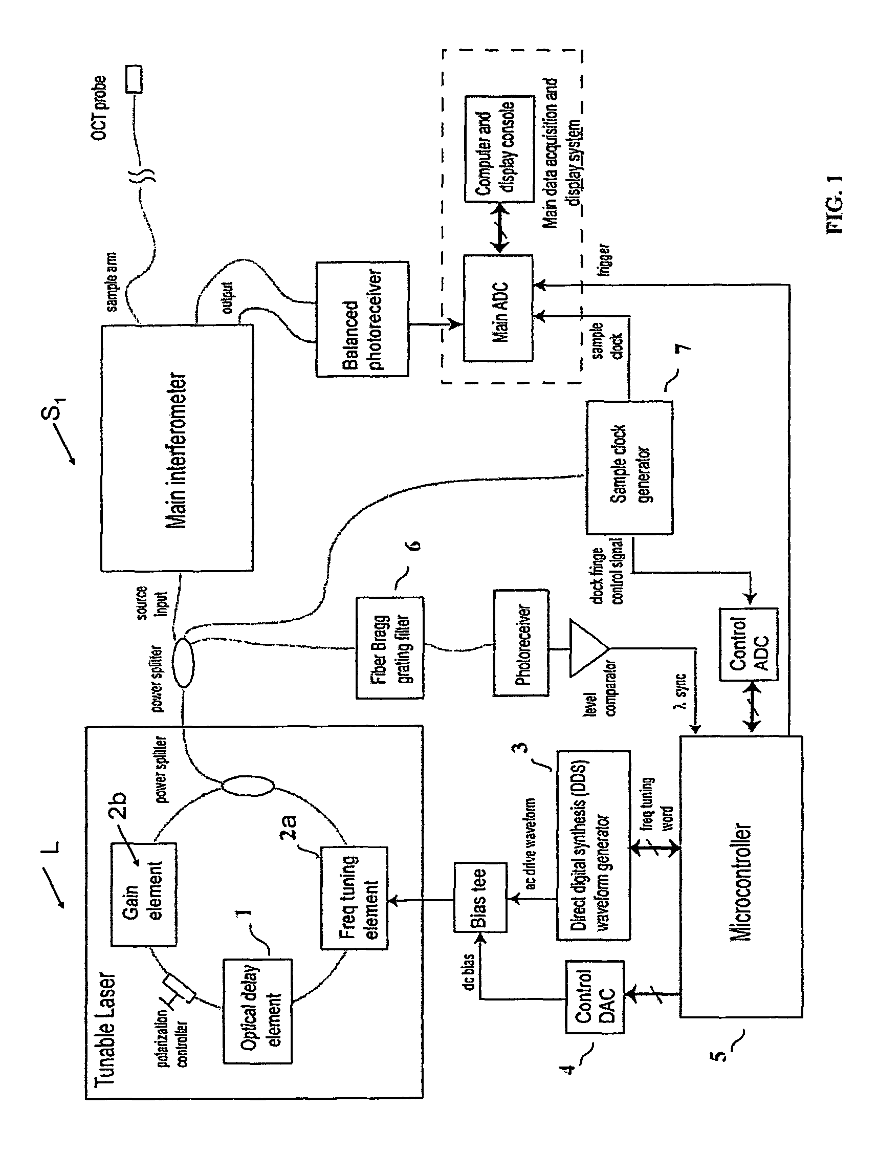
[0010]The apparatus can include a sample clock generator, where the sample clock generator can be configured to clock an analog-to-digital converter. The analog-to-digital converter can be configured to sample interference signals at an output of a main interferometer. The apparatus can include a digital control system configured to stabilize a drive frequency of the frequency tuning element of the Fourier-domain mode-locked laser using at least one control signal derived from the sample clock generator. The Fourier-domain mode-locked laser can include an optical delay element that includes a pair of fiber coils whose relative orientations are adjusted to reduce the effects of polarization mode dispersion.
[0014]The method can further include the step of generating a pair of balanced signals with a quadrature phase relationship for dual-channel acquisition of OCT signals from the main interferometer using a 4×4 coupler, whereby only a single ADC clock signal from the sample clock generator is required. The step of optimizing the drive frequency can include measuring the instantaneous RMS amplitude Φ(t) of the interference signal at the output of the sample clock interferometer's photoreceiver at the time τ indicated by transmission of a pulse through a fiber-Bragg filter with a narrow passband in the vicinity of the zero-dispersion wavelength of the optical delay element and adjusting the frequency of a direct digital synthesis (DDS) generator to maximize the value of Φ(t).
[0016]In another aspect, the invention relates to an optical coherence tomography data collection apparatus, the apparatus includes an interferometer having an input and an output, an analog-to-digital converter configured to sample interference signals from the output, a first gain element, a second gain element, where each gain element can have a different gain dependence on polarization, a Fourier-domain mode-locked laser having a laser cavity, where the laser can be in optical communication with the interferometer. The laser can include a frequency tuning element in optical communication with the first gain element, the first gain element disposed within the laser cavity, the second gain element disposed outside the cavity, a sample clock generator configured to clock an analog-to-digital converter, and a digital control system configured to stabilize a drive frequency of the frequency tuning element of the laser, using a control signal derived from the sample clock generator. The gain dependence on polarization of the first gain element can be less than the gain dependence on polarization of the second gain element. The laser can include an optical delay element that includes a pair of fiber coils whose relative orientations are adjusted to reduce the effects of polarization mode dispersion.
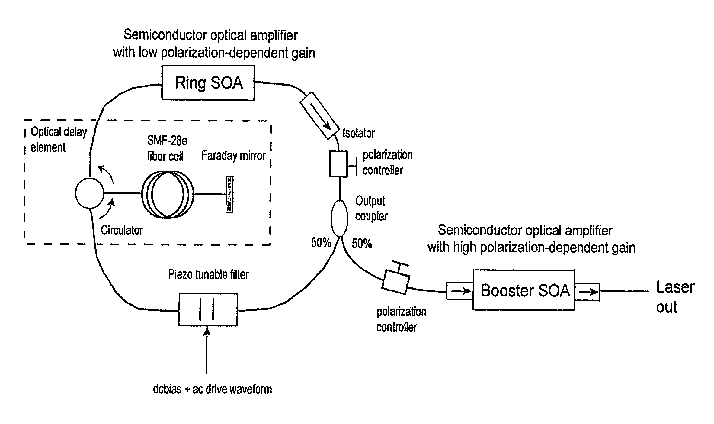
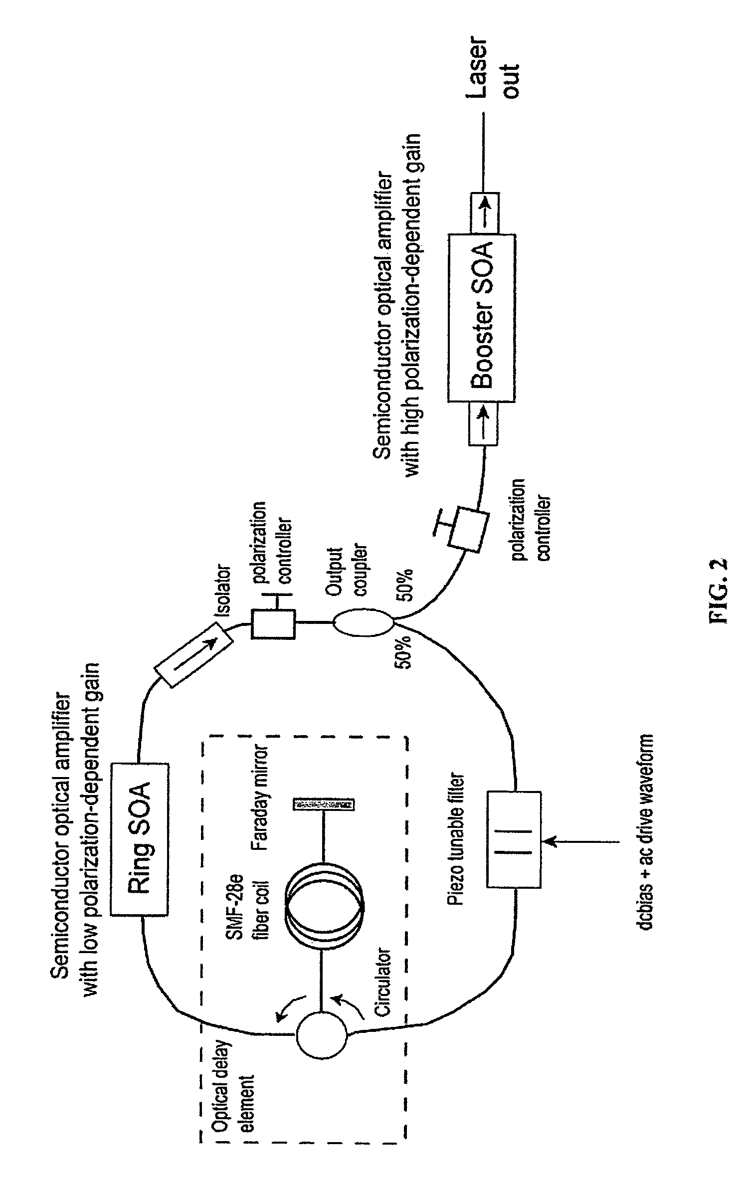
[0019]In one embodiment of the invention, a semiconductor optical amplifier (SOA) in a laser ring is chosen to provide low polarization-dependent gain (PDG) and a booster semiconductor optical amplifier, outside of the ring, is chosen to provide high polarization-dependent gain. The use of a semiconductor optical amplifier with low polarization-dependent gain nearly eliminates variations in the polarization state of the light at the output of the laser, but does not eliminate the intra-sweep variations in the polarization state at the output of the laser, which can degrade the performance of the SS-OCT system. Some of the embodiments disclosed herein overcome variations in both the amplitude and polarization, because the booster semiconductor optical amplifier provides sufficient amplification in a single polarization axis to reach gain saturation at all wavelengths, in spite of the polarization variations at the output of the low polarization-dependent gain ring semiconductor optical amplifier.
[0020]One objective of this invention is to present methods for stabilization of the polarization state of light circulating within the long-path ring cavity of an FDML laser. These methods improve the performance and manufacturability of SS-OCT systems based on the FDML principle.
[0021]Another objective of the present invention is to describe opto-electronic methods and devices for generating a stable sample clock for direct acquisition of interferometric systems from various types of SS-OCT systems. These methods reduce phase noise, expand the dynamic range, and increase the acquisition speed of the acquired interference signals.

Problems solved by technology

The methods detailed herein overcome disadvantages of previous implementations of SS-OCT systems, which include poor noise performance, limited scan range, the effects the birefringence and dispersion properties of the laser cavity, phase jitter, and sampling speed limitations.

Method used


Image

  • Methods and apparatus for swept-source optical coherence tomography
  • Methods and apparatus for swept-source optical coherence tomography
  • Methods and apparatus for swept-source optical coherence tomography

Examples


Embodiment Construction

the clock fringe control signal (RMS fringe amplitude) for optimum and non-optimum (too low or too high) adjustment of the frequency of the waveform driving the frequency tuning element in the FDML laser according to one specific embodiment of the invention.

[0040]FIG. 14 illustrates a specific embodiment of a feedback control loop for optimization and stabilization of the dc bias voltage applied to the tuning element in the FDML laser according to an illustrative embodiment of the invention.

[0041]FIG. 15 shows the typical highly resonant frequency response of a piezo-actuated Fabry-Perot tunable filter according to an illustrative embodiment of the invention.

[0042]FIG. 16 illustrates the principle of Fourier synthesis on which an exemplary actuator linearization method is based according to an illustrative embodiment of the invention.

[0043]FIG. 17 shows an example of a configuration for synthesized harmonic linearization of a piezo-actuated Fabry-Perot tunable filter according to an...


PUM


Abstract

In one embodiment of the invention, a semiconductor optical amplifier (SOA) in a laser ring is chosen to provide low polarization-dependent gain (PDG) and a booster semiconductor optical amplifier, outside of the ring, is chosen to provide high polarization-dependent gain. The use of a semiconductor optical amplifier with low polarization-dependent gain nearly eliminates variations in the polarization state of the light at the output of the laser, but does not eliminate the intra-sweep variations in the polarization state at the output of the laser, which can degrade the performance of the SS-OCT system.

Description

RELATED APPLICATIONS[0001]This application claims priority to U.S. Provisional Patent Application 60 / 879,880 filed on Jan. 10, 2007, the disclosure of which is herein incorporated by reference in its entirety.FIELD OF INVENTION[0002]This invention relates to the field of optical imaging and more specifically to the design and implementation of optical coherence tomography (OCT) systems that employ swept-frequency lasers as light sources.BACKGROUND[0003]Optical coherence tomography (OCT) is an interferometric imaging technique with widespread applications in ophthalmology, cardiology, gastroenterology and other fields of medicine. Huang D, Swanson E A, Lin C P, Schuman J S, Stinson W G, Chang W, Hee M R, Flotte T, Gregory K, Puliafito C A, and Fujimoto J G, “Optical coherence tomography,”Science, Vol 254, 1178-1181 (1991). The ability to view subsurface structures with high resolution (2-15 μm) through small-diameter fiber-optic probes makes OCT especially useful for minimally invasi...

Claims


Application Information

Patent Timeline
Patent Type & Authority Patents(United States)
IPC IPC(8): H01S5/00H01S3/098
CPCA61B5/0066A61B5/0073G01B9/02091G01B9/02069G01B9/02004G01B2290/60H01S3/1062H01S5/141H01S5/146H01S5/5036G01B9/02043G01B2290/25
Inventor SCHMITT, JOSEPH M.
Owner LIGHTLAB IMAGING
Learn More