Magnetic tunnel transistor having a base structure that provides polarization of unpolarized electrons from an emitter based upon a magnetic orientation of a free layer and a self-pinned layer

a tunnel transistor and self-pinned layer technology, applied in the field of magnetic tunnel transistors, can solve the problems of reduced collector current, defect of conventional spin-valve transistors, and low collector current (isub>c/sub>), and achieve the effect of increasing the magnetocurrent ratio

Inactive Publication Date: 2011-03-29
WESTERN DIGITAL TECH INC
View PDF26 Cites 12 Cited by
  • Summary
  • Abstract
  • Description
  • Claims
  • Application Information

AI Technical Summary

Benefits of technology

[0016]To overcome the limitations in the prior art described above, and to overcome other limitations that will become apparent upon reading and understanding the present specification, embodiment

Problems solved by technology

However, even though spin-valve transistors are known to exhibit an extremely high MR ratio of several hundreds percent at certain temperatures, conventional spin-valve transistors have a defect in that a collector current (IC) is extremely low.
Nevertheless, since the scattered electrons are incapable of flowing into the collector due to a strong diffraction effect at the interface between the base and the collector, the collector current is decreased.
Another reason for a small collector current is because of limited collection efficiency due to a small difference between two Schottky barrier heights.
The resulting low transfer ratio of collector current-to-emitter current (IC/IE) in the spin-valve transist

Method used


Image

  • Magnetic tunnel transistor having a base structure that provides polarization of unpolarized electrons from an emitter based upon a magnetic orientation of a free layer and a self-pinned layer
  • Magnetic tunnel transistor having a base structure that provides polarization of unpolarized electrons from an emitter based upon a magnetic orientation of a free layer and a self-pinned layer
  • Magnetic tunnel transistor having a base structure that provides polarization of unpolarized electrons from an emitter based upon a magnetic orientation of a free layer and a self-pinned layer

Examples


Embodiment Construction

[0032]In the following description of the embodiments, reference is made to the accompanying drawings that form a part hereof, and in which is shown by way of illustration the specific embodiments in which the invention may be practiced. It is to be understood that other embodiments may be utilized because structural changes may be made without departing from the scope of the embodiments of the present invention.

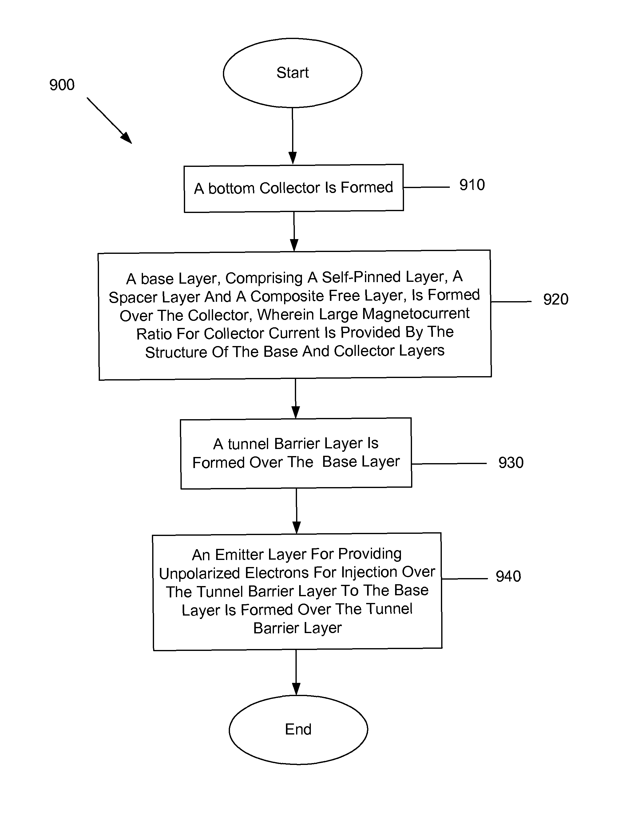
[0033]Embodiments of the present invention provide a method and apparatus for providing a magnetic tunnel transistor having a bottom collector and self-pinned spin-valve providing an enhanced magnetocurrent ratio. Resistance in a self-pinned emitter is lowered by eliminating a thick resistive adjacent anti-ferromagnetic pinning layer. An easier manufacturing process is provided because the semiconductor material of the collector may be formed on the bottom first as it requires a high temperature fabrication process that degrades properties of the magnetic layers of a magneti...


PUM


Abstract

A magnetic tunnel transistor (MTT) is formed having an emitter that is configured to provide unpolarized electrons. A composite base is configured to provide polarization of the unpolarized electrons injected into the base by the emitter based upon a magnetic orientation of the free layer and the self-pinned layer of the base.

Description

RELATED APPLICATION[0001]This application is a continuation-in-part of U.S. application Ser. No. 10 / 428,474, filed May 2, 2003, which is hereby incorporated by reference.BACKGROUND OF THE INVENTION[0002]1. Field of the Invention[0003]The present invention relates in general to magnetic heads for magnetic storage systems and more particularly to a magnetic tunnel transistor having a bottom collector and self-pinned spin-valve providing an enhanced magnetocurrent ratio.[0004]2. Description of Related Art[0005]Magnetic recording is a key and invaluable segment of the information-processing industry. While the basic principles are one hundred years old for early tape devices, and over forty years old for magnetic hard disk drives, an influx of technical innovations continues to extend the storage capacity and performance of magnetic recording products.[0006]For hard disk drives, the areal density or density of written data bits on the magnetic medium has increased by a factor of more th...

Claims


Application Information

Patent Timeline
IPC IPC(8): G11B5/33
CPCB82Y10/00B82Y25/00G01R33/098G11B5/3909G11B5/3929G11C11/16H01L43/08G11B2005/3996G11C11/161G11C11/1673G11C11/1675H10N50/10
Inventor GILL, HARDAYAL SINGH
Owner WESTERN DIGITAL TECH INC
Why Eureka
Try Eureka