Systems and methods for testing and diagnosing delay faults and for parametric testing in digital circuits

a digital circuit and delay fault technology, applied in the field of integrated circuit testing and diagnosis, can solve the problems of increasing current consumption, reducing voltage swings, and affecting the performance of digital circuits

Inactive Publication Date: 2011-03-29
DFT MICROSYST
View PDF76 Cites 9 Cited by
  • Summary
  • Abstract
  • Description
  • Claims
  • Application Information

AI Technical Summary

Problems solved by technology

Various new failure mechanisms plague modern nanometer-scale integrated circuits.
Reduced voltage swings, increased current consumption, the introduction of new materials, and unprecedented densities render such circuits increasingly sensitive to phenomena like local temperature variations within a chip, local power supply voltage variations, clock jitter, and small resistive / capacitive defects.
In the present state of the art, conventional test methods do not cover timing-related faults effectively.
Thus, the latter represent a significant risk of increased test escapes, which are defined as failing parts that are not caught before shipment, or increased reliability escapes, which are defined as functional parts that suffer from premature failure in the field.
When it comes to testing chips in large volume, ring-oscillator monitors become ineffective since they require calibration and offer too little resolution.
Small delay faults are notorious in that they pass conventional structural test methods without being detected.
Unfortunately, a failing over-speed vector does not necessarily mean the part being tested is really defective since the latter was not designed to operate at this fast clock frequency in the first place.

Method used


Image

  • Systems and methods for testing and diagnosing delay faults and for parametric testing in digital circuits
  • Systems and methods for testing and diagnosing delay faults and for parametric testing in digital circuits
  • Systems and methods for testing and diagnosing delay faults and for parametric testing in digital circuits

Examples


first embodiment

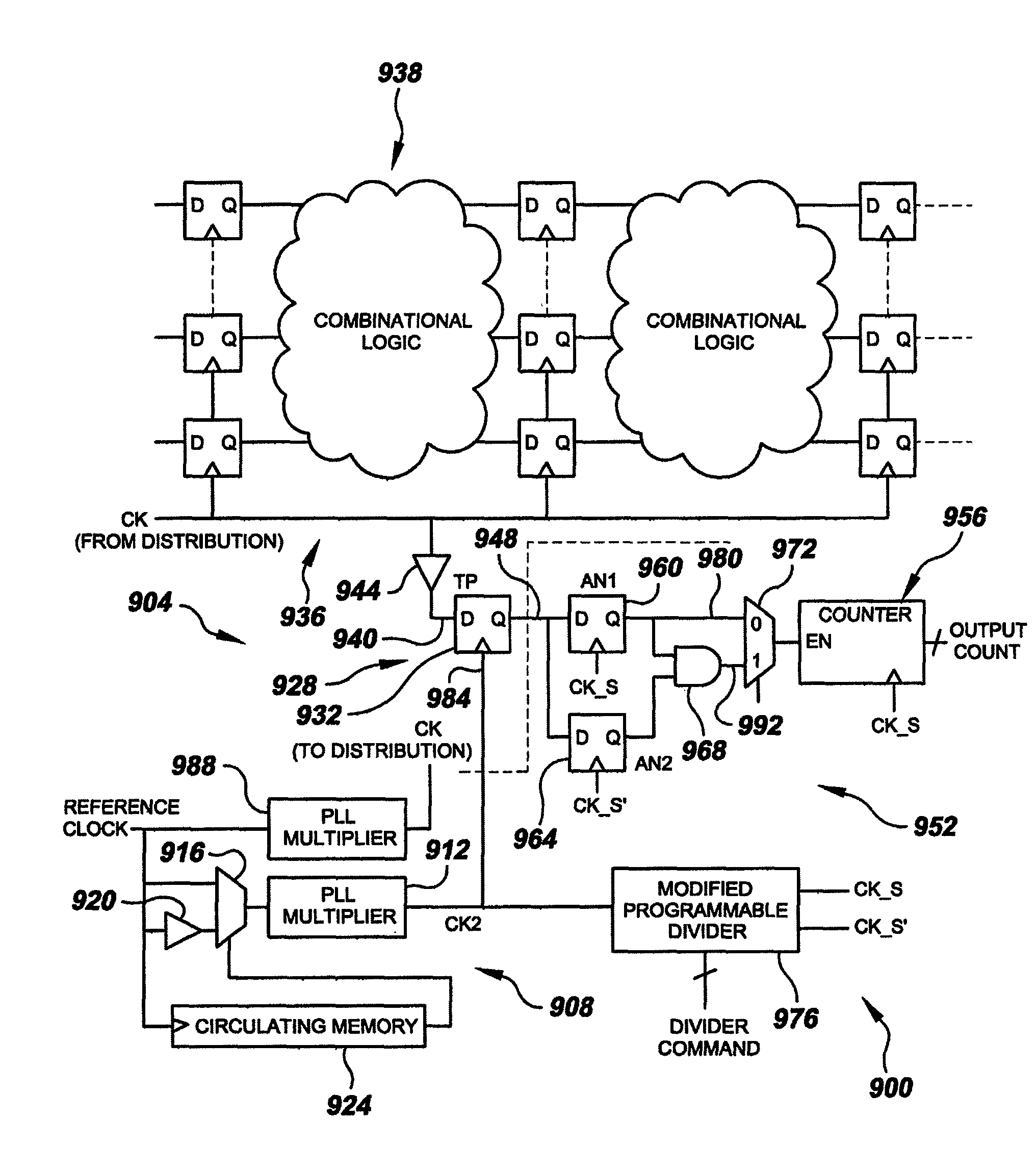
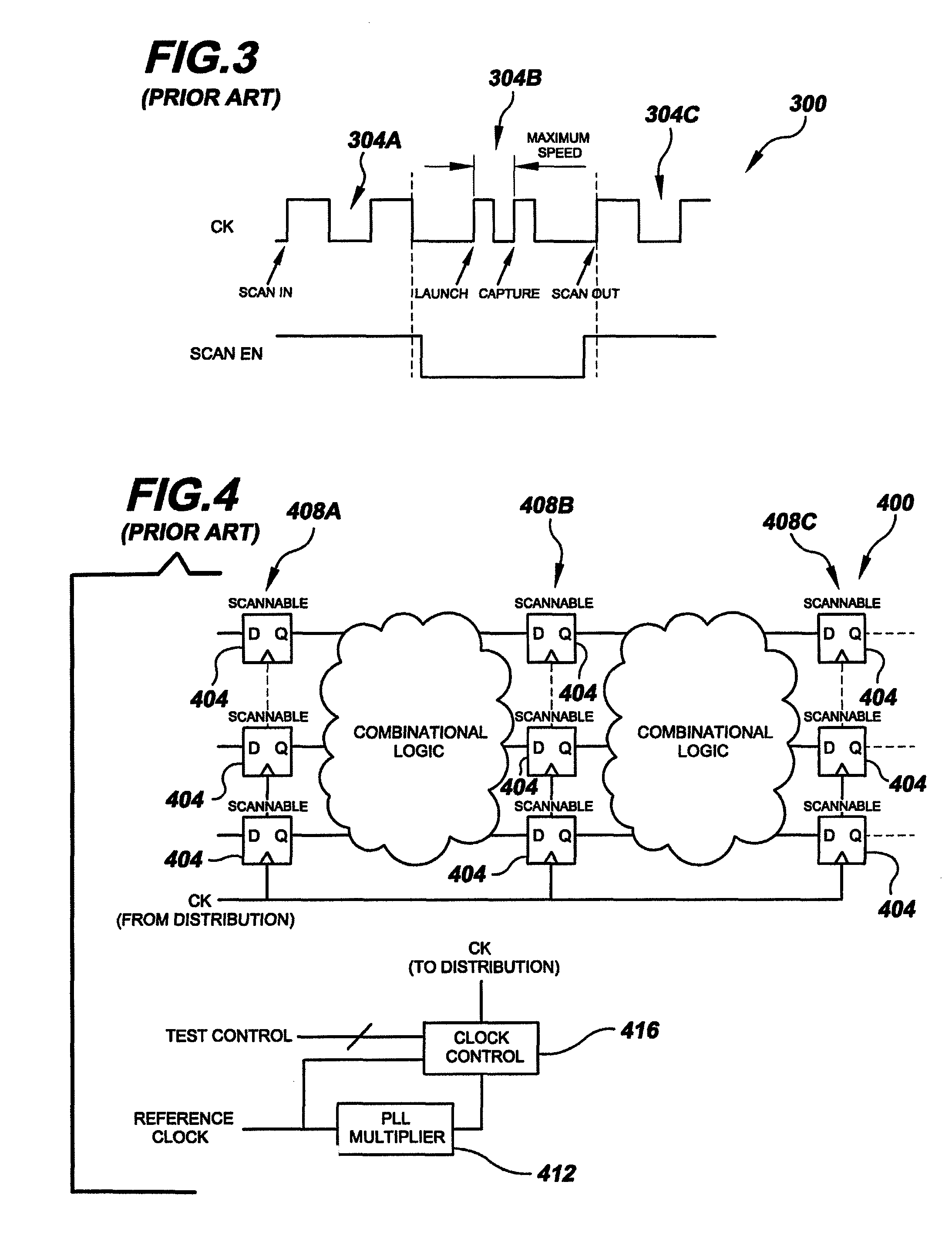
the present invention relates to testing one or more small delay paths without over-clocking an entire circuit. This can be achieved through special circuitry and connections as illustrated in integrated circuit 600 of FIG. 6 and discussed below. To highlight the special circuitry and connections, integrated circuit 600 is based on conventional integrated circuit 400 of FIG. 4. That is, like integrated circuit 400 of FIG. 4, integrated circuit 600 includes two combinational logic blocks 604A-B and three scan chains 608A-C each containing scannable memory elements 612. However, as can be seen in FIG. 6, circuit 600 includes one or more additional scannable flip-flops (or other memory element) (only one is illustrated at element numeral 616) placed at selected locations in the circuit. The selected locations are predetermined based on the circuit design (e.g. a small delay path situation as in FIG. 5) as well as topology. CAD tools exist for performing topology-based analysis like the...


PUM


Abstract

Delay-fault testing and parametric analysis systems and methods utilizing one or more variable delay time-base generators. In embodiments of the delay-fault testing systems, short-delay logic paths are provided with additional scan-chain memory elements and logic that, in conjunction with the one or more variable-delay time-base generators, provides the effect of over-clocking without the need to over-clock. Related methods provide such effective over-clocking. In embodiments of parametric analysis systems, test point sampling elements and analysis circuitry are clocked as a function of the output of the one or more variable-delay time-base generators to provide various parametric analysis functionality. Related methods address this functionality.

Description

FIELD OF INVENTIONThe present invention relates generally to integrated circuits testing and diagnosis. More particularly, the present invention is directed to systems and methods for testing and diagnosing delay faults and for parametric testing in digital circuits.BACKGROUNDVarious new failure mechanisms plague modern nanometer-scale integrated circuits. Reduced voltage swings, increased current consumption, the introduction of new materials, and unprecedented densities render such circuits increasingly sensitive to phenomena like local temperature variations within a chip, local power supply voltage variations, clock jitter, and small resistive / capacitive defects. A common theme among these effects is that they are not uncovered using conventional debug and test methods. In other words, failures due to these effects do not manifest themselves in conventional ways; rather, they are timing related. Simplistically, they affect the maximum speed at which a circuit can operate in its ...

Claims


Application Information

Patent Timeline
Patent Type & Authority Patents(United States)
IPC IPC(8): G01R31/26G06F11/26
CPCG01R31/31858
Inventor HAFED, MOHAMED M.
Owner DFT MICROSYST
Why Eureka
Try Eureka