
Optical wavelength conversion element having a cesium-lithium-borate crystal

a technology of optical wavelength conversion and cesium lithium bore, applied in the field of optical wavelength conversion elements, can solve the problems of deterioration in quality or laser damage, low power obtained when a high-output ultraviolet laser is generated, and change in internal refractive index, etc., to achieve high reliability in long-term operation, excellent operability, and high performance.

Active Publication Date: 2011-05-24
OSAKA UNIV +1
View PDF20 Cites 13 Cited by
  • Summary
  • Abstract
  • Description
  • Claims
  • Application Information

AI Technical Summary

Benefits of technology

The present invention provides a novel optical wavelength conversion element that can improve the output power of an ultraviolet laser and can be used at room temperature. The element uses a cesium-lithium-borate crystal with a low content of water impurities, which allows for high transmittance and low loss. The manufacturing method involves heating the crystal at high temperatures for at least 24 hours to remove moisture. The optical wavelength conversion device, ultraviolet laser irradiation apparatus, and laser processing system, all use the optical wavelength conversion element, which exhibits high performance, reliability, and operability with short rise time. The manufacturing method allows for easy manufacturing of the element.

Problems solved by technology

However, since the CLBO crystal is deliquescent, there is a problem in that the crystal optical surface reacts with, for example, moisture in the atmosphere, which results in a deterioration in quality or laser damage and also causes a change in internal refractive index.
Therefore, in order to solve both the problems of the aforementioned moisture prevention and the generation of the phase mismatch region, there is a method in which a CLBO crystal is used in the state where it is heated at 150° C. However, since in this method, it is difficult to avoid the effect of self-heating, the output power obtained when a high output ultraviolet laser is generated tends to be lower than the theoretical value obtained with no consideration given to the heat effect.
This, however, works as a factor that causes damage and deterioration of the CLBO crystal, and thereby reliability of long-term operation is deteriorated, which is a problem.
The vicinity of the laser beam condensing part inside the crystal is subjected to an environment where an “internal laser damage” in which heat cracks occur due to the heat generated by the ultraviolet laser tends to be caused.
Furthermore, since the CLBO crystal has the property that the refractive index value decreases with heat generation, the CLBO crystal exhibits a “thermal lens effect” in which the diameter of a laser beam light collected for improving the ultraviolet laser conversion efficiency disadvantageously increases.
Moreover, the use of a CLBO crystal in the state where it is heated at 150° C. requires time for starting up (activating) the ultraviolet laser irradiation apparatus and therefore there has been a problem in operability.
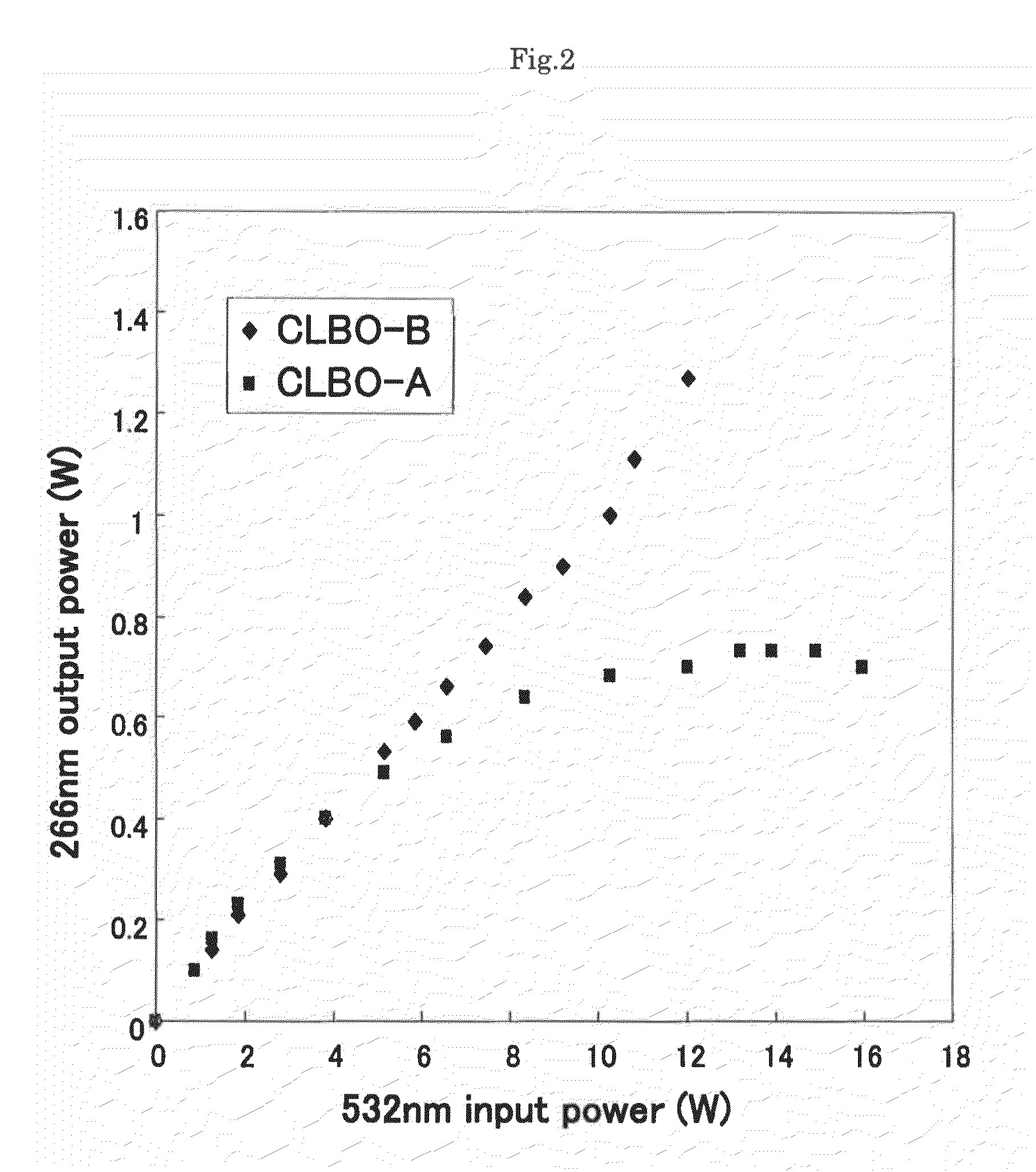
However, the CLBO crystal produced by this technique has a problem in that an output saturation phenomenon occurs in which the output power of ultraviolet laser generated also increases up to a certain region with an increase in source laser input power, but when the input power exceeds a certain value, the output power stops increasing.
Such use at room temperature and improvement in ultraviolet laser output also are problems to be solved in all the cesium-lithium-borate crystals including the CLBO crystal.

Method used


Image

  • Optical wavelength conversion element having a cesium-lithium-borate crystal
  • Optical wavelength conversion element having a cesium-lithium-borate crystal
  • Optical wavelength conversion element having a cesium-lithium-borate crystal

Examples


example 1

[0069]Next, an example of an embodiment of the present invention is described together with comparative examples. The present invention, however, is not limited by the following example and comparative examples by any means.

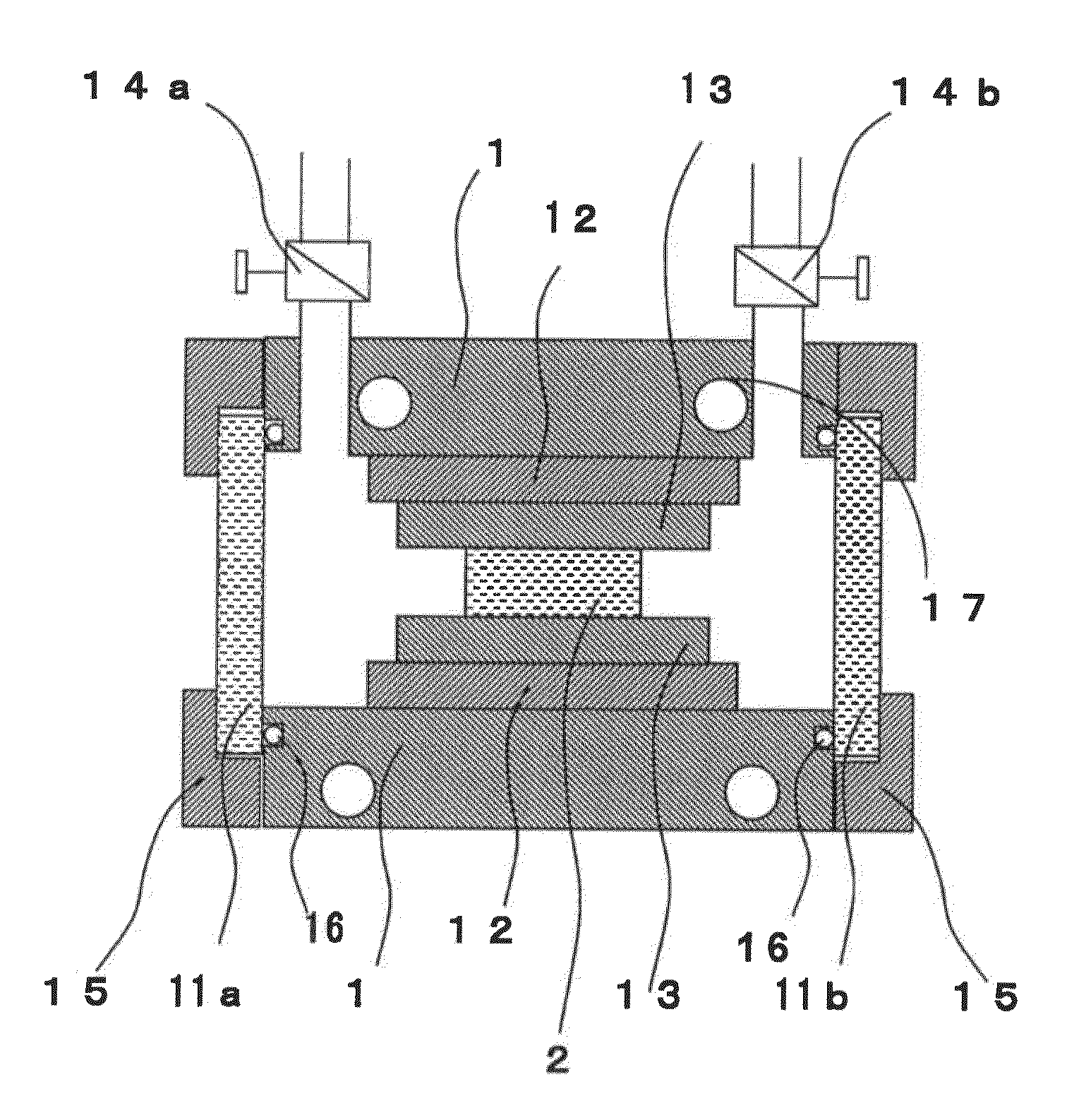
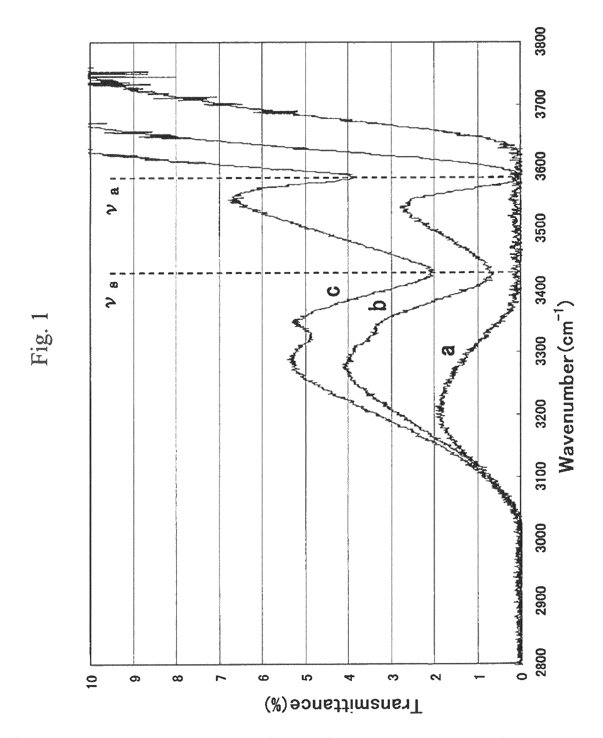
[0070]First, a CLBO crystal was cut in the orientation of (θ, φ)=(61.9°, 45°) and was then optically polished, and thereby a 10-mm long element with a cross-section of 5×5 mm2 was obtained. This element was placed inside the optical cell 1 of the wavelength conversion device shown in FIG. 4 and was heated in the atmosphere at 150° C. for 120 hours. Thereafter, the atmosphere gas was replaced by argon gas, and the element further was heated at 150° C. for 72 hours, with the argon gas being allowed to flow at a flow rate of 25 ml / min. Thus, an optical wavelength conversion element of this example was obtained. With respect to this optical wavelength conversion element, the transmission spectrum was measured with unpolarized infrared light using a Fourier transform ...


PUM

PropertyMeasurementUnit
transmittanceaaaaaaaaaa
temperatureaaaaaaaaaa

Abstract

An optical wavelength conversion element includes a cesium-lithium-borate crystal processed into a 10-mm long optical element cut in an orientation that allows a fourth harmonic of a Nd:YAG laser to be generated. A transmittance (Ta) at 3589 cm−1 in an infrared transmission spectrum of the optical element is used as an index that indicates a content of water impurities in the crystal and is independent of a polarization direction. An actual measurement of the transmittance Ta is at least 1%, without taking into account loss at an optically polished surface of the crystal. A wavelength conversion device, a ultraviolet laser irradiation apparatus, a laser processing system, and a method of manufacturing an optical wavelength conversion element are also described.

Description

CROSS-REFERENCE TO RELATED APPLICATIONS[0001]This application is a Continuation of International Patent Application No. PCT / JP2007 / 055072, filed Mar. 14, 2007, and claims priority to Japanese Patent Application No. 2006-075753, filed Mar. 18, 2006. The contents of PCT / JP2007 / 055072 are incorporated herein by reference in their entirety.BACKGROUND OF THE INVENTION[0002]1. Field of the Invention[0003]The present invention relates to optical wavelength conversion elements, methods of manufacturing optical wavelength conversion elements, wavelength conversion devices, ultraviolet laser irradiation apparatuses, and laser processing systems.[0004]2. Discussion of the Background[0005]In an ultraviolet laser, a method is employed in which ultraviolet light is generated from a source laser that emits light in the infrared region through multiple uses of a nonlinear optical effect of an optical wavelength conversion element. In the method, for an optical wavelength conversion element that is ...

Claims


Application Information

Patent Timeline
Patent Type & Authority Patents(United States)
IPC IPC(8): G02F1/35H01S3/10
CPCG02F1/37G02F1/3551G02F2001/354G02F2001/3505G02F1/3505G02F1/354
Inventor YOSHIMURA, MASASHISASAKI, TAKATOMOMORI, YUSUKENISHIOKA, MUNEYUKIKATSURA, TOMOTAKAKOJIMA, TETSUONISHIMAE, JUNICHI
Owner OSAKA UNIV
Learn More