

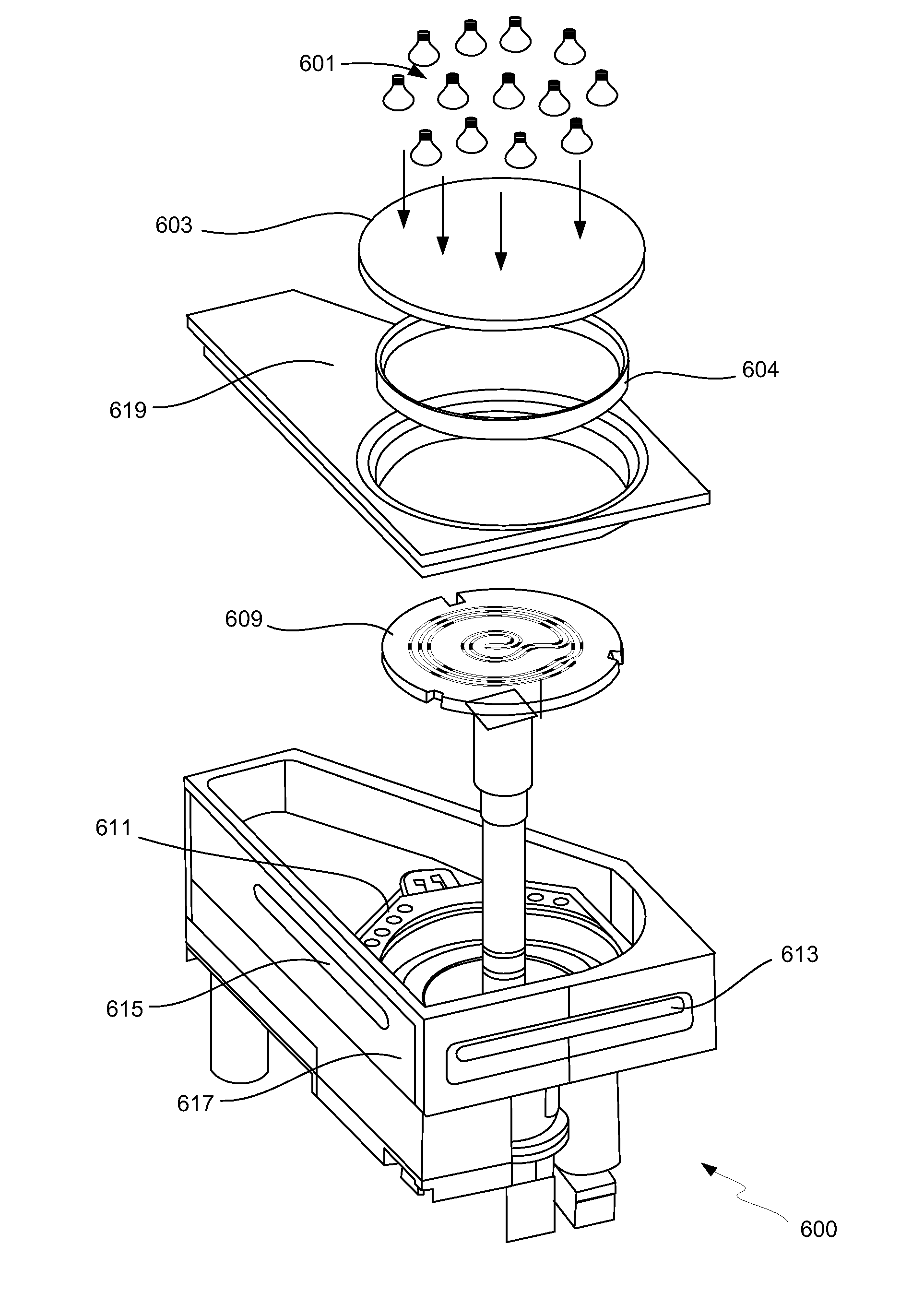
Load lock design for rapid wafer heating
a technology of loading lock and wafer, which is applied in the direction of electrostatic spraying apparatus, electrical apparatus, spraying apparatus, etc., can solve the problems of affecting yield and manufacturing costs, wasting valuable processing time, and uniformity of wafers, so as to achieve uniform and rapid heating and improve throughput
- Summary
- Abstract
- Description
- Claims
- Application Information
AI Technical Summary
Benefits of technology
Problems solved by technology
Method used
Image

Examples
Embodiment Construction
[0023]In the following detailed description of the present invention, a number of specific embodiments are set forth in order to provide a thorough understanding of the invention. However, as will be apparent to those skilled in the art, the present invention may be practiced without these specific details or by using alternate elements or processes. In some descriptions herein, well-known processes, procedures, and components have not been described in detail so as not to unnecessarily obscure aspects of the present invention.
[0024]In this application, the terms “wafer” and “substrate” and terms “substrate support” and “pedestal” will be used interchangeably. The following detailed description assumes the invention is implemented on a wafer. However, the invention is not so limited. The work piece may be of various shapes, sizes, and materials. In addition to semiconductor wafers, other work pieces that may take advantage of this invention include various articles such as display b...
PUM
 Abstract
Description
Claims
Application Information