
Phosphor, method for producing same, and light-emitting device

a technology of phosphor and phosphor, which is applied in the field of phosphor, can solve the problems of amorphous thin films of phosphors based on aln, and the tendency to decrease the light intensity of phosphors, and achieve the effect of enhancing the emission intensity and hardly lowering the emission intensity

Active Publication Date: 2011-11-15
NAT INST FOR MATERIALS SCI
View PDF28 Cites 5 Cited by
  • Summary
  • Abstract
  • Description
  • Claims
  • Application Information

AI Technical Summary

Benefits of technology

The present invention provides a new phosphor that emits light with high intensity upon excitation with an electron beam, which is in high demand for applications such as plasma displays and white light LEDs. The new phosphor has better emission properties and durability compared to existing phosphors. The invention also provides a method for manufacturing the new phosphor and a lighting device and image display device that use the new phosphor.

Problems solved by technology

However, as a result of the phosphor being exposed to such excitation source, the luminance of the phosphor tends to decrease.
However, these kinds of phosphors based on AlN are amorphous thin films which are not suitable for any application in a light or an image display device.

Method used


Image

  • Phosphor, method for producing same, and light-emitting device
  • Phosphor, method for producing same, and light-emitting device
  • Phosphor, method for producing same, and light-emitting device

Examples


examples 1 to 43

[0092]As powdery raw materials, aluminum nitride powder having a specific surface area of 3.3 m2 / g and an oxygen content of 0.79% (Tokuyama Corp., F grade), aluminum oxide powder of 99.99% purity having a specific surface area of 13.6 m2 / g (Taimei Chemicals Co., Ltd., Taimicron grade), manganese carbonate powder of 99.9% purity (Kojundo Chemical Lab. Co., Ltd., reagent grade), and europium oxide powder and cerium oxide powder of 99.9% purity (Shin-etsu Chemical Co., Ltd.) were used.

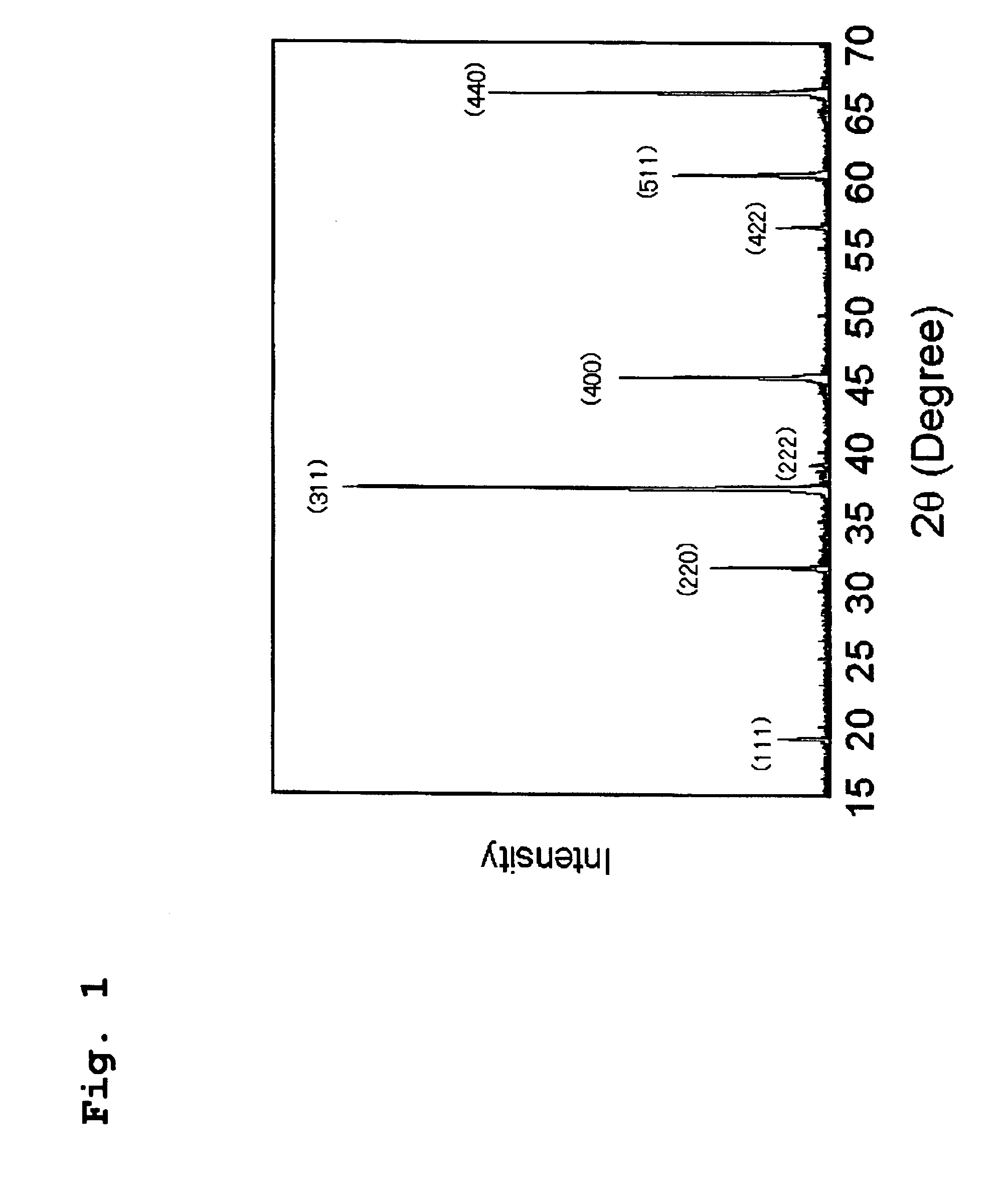
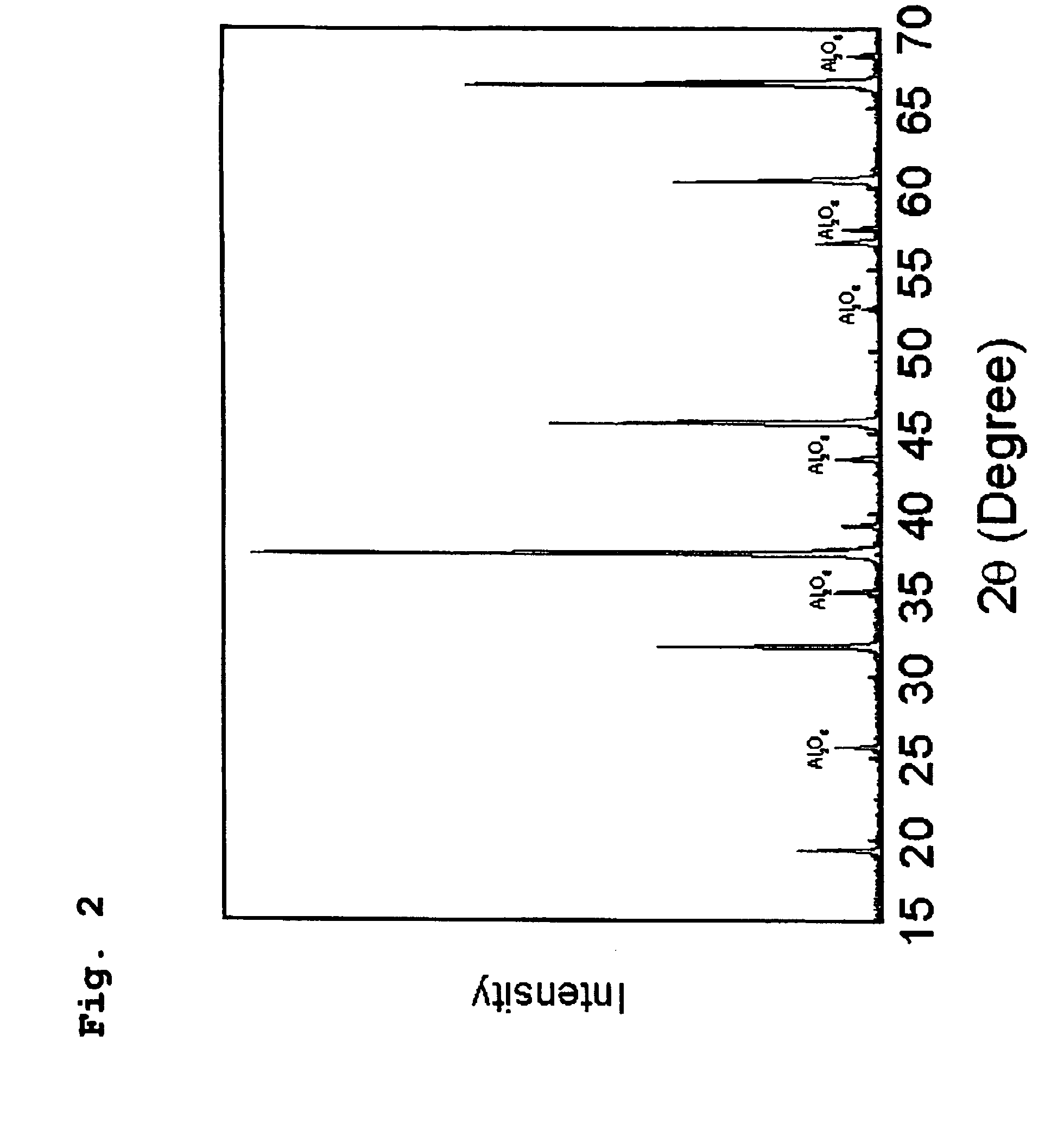
[0093]First, in order to synthesize Al7O9N, which is the theoretical composition of AlON, powdery Al2O3 and AlN materials were weighed so that a composition of 75 mol % Al2O3-25 mol % AlN was obtained. After mixing the weighed composition with a mortar and pestle made of silicon nitride, the resultant mixture was charged into a boron nitride crucible having a diameter of 20 mm and a height of 20 mm, and the charged crucible was set into a graphite resistance heating-type electric furnace. Firing operation...

example 44 to 46

[0100]The same powdery raw materials as employed in Examples 1 to 43, silicon nitride powder having a mean particle diameter of 0.5 μm, oxygen content of 0.93 wt. %, and α-type content of 92% (Ube Industries, Ltd., E10 grade), calcium carbonate powder of 99.9% purity (Kojundo Chemical Laboratory, Co., Ltd., reagent grade), and magnesium oxide powder (Konoshima Chemical Co., Ltd.) were used. Table 1 also summarizes design compositions of Examples 44 to 46.

[0101]In Example 44, in order to synthesize a composition of Mn0.974Si19.4Al21.9O28N29.7, powdery raw materials were weighed in a proportion of 5.34 mass % MnCO3, 43.3 mass % Si3N4, 7.55 mass % AlN, and 43.83 mass % Al2O3.

[0102]In Example 45, in order to synthesize a composition Mn0.536Mg35.6Al11.5O50.3N2.03, powdery raw materials were weighed in a proportion of 2.99 mass % MnCO3, 67.57 mass % MgO, 4.033 mass % AlN, and 23.41 mass % Al2O3.

[0103]In Example 46, in order to synthesize a composition of Mn0.536Ca35.6Al11.5O50.3N2.03, pow...


PUM

PropertyMeasurementUnit
wavelength rangeaaaaaaaaaa
wavelengthaaaaaaaaaa

Abstract

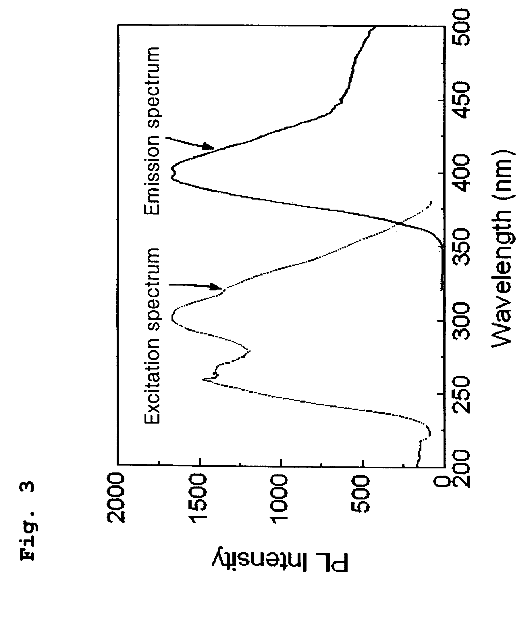
Disclosed are violet, blue, and green phosphors having excellent durability and high luminance. Specifically disclosed is a phosphor which contains a metal element M (M is at least one element selected from among Mn, Ce, Pr, Nd, Sm, Eu, Gd, Tb, Dy, Tm and Yb) for constituting a metal ion, which is solid-solubilized in an AlON crystal, an AlON solid solution crystal or an inorganic crystal having the same crystal structure as AlON. The phosphor is capable of emitting fluorescence having a peak in the wavelength range from 300 nm to 700 nm. Also disclosed is a method for producing such a phosphor. Further disclosed are an illuminating device and an image display each containing such a phosphor.

Description

PRIORITY CLAIM[0001]The present application is a U.S. National Stage Application under 35 U.S.C. 371 of PCT / JP2007 / 053324, filed on Feb. 22, 2007, which claims priority to Japanese Patent Application 2006-047729, filed on Feb. 24, 2006.BACKGROUND OF THE INVENTION[0002]1. Field of the Invention[0003]The present invention relates to a phosphor comprising, as a host crystal, an AlON (oxynitride aluminum) crystal, an AlON solid solution crystal, or an inorganic crystal having the same crystal structure as AlON; a manufacturing method thereof; and an application thereof. More specifically, the application relates to a lighting device and an emission apparatus of an image display device utilizing features of the phosphor, that is, property of emitting light having a peak in a wavelength range of 300 nm or longer and 700 nm and shorter.[0004]2. Description of Related Art[0005]The phosphor is utilized in a fluorescent display tube (VFD: vacuum-fluorescent display), a field emission display ...

Claims


Application Information

Patent Timeline
Patent Type & Authority Patents(United States)
IPC IPC(8): H01J29/20H01J31/12H01J31/15H01J31/20H01L33/00H01S5/022C09K11/64H01L33/48H01L33/50H01L33/56H01L33/60H01L33/62
CPCC04B35/44C04B35/58C04B35/581C04B35/597C04B35/6262C09K11/0883C09K11/641C09K11/7721C09K11/7734C04B2235/3206C04B2235/3208C04B2235/3217C04B2235/3224C04B2235/3229C04B2235/3262C04B2235/3865C04B2235/3878C04B2235/3895C04B2235/442C04B2235/5409C04B2235/5445C04B2235/81H01L2224/48091H01L2224/48247H01L2924/181H01L2224/32245H01L2224/73265C09K11/77216C09K11/77346C09K11/77348H01L2924/00014H01L2924/00012H01L2924/00
Inventor XIE, RONG-JUNHIROSAKI, NAOTO
Owner NAT INST FOR MATERIALS SCI
Learn More