Refractory crucibles capable of managing thermal stress and suitable for melting highly reactive alloys

a technology of crucibles and reactive alloys, applied in the direction of manufacturing converters, furniture, lighting and heating apparatus, etc., can solve the problems of crucible cracking, crucible life reduction, and inclusions in the component being cas

Active Publication Date: 2011-11-22
GENERAL ELECTRIC CO
View PDF11 Cites 13 Cited by
  • Summary
  • Abstract
  • Description
  • Claims
  • Application Information

AI Technical Summary

Problems solved by technology

This is because melting and casting from ceramic crucibles can introduce significant thermal stress on the crucible, which can result in the crucible cracking.
Such cracking can reduce crucible life and cause inclusions in the component being cast.
Moreover, difficulties can arise when melting highly reactive alloys, such as TiAl, due to the reactivity of the elements in the alloy at the temperatures needed for melting to occur.
As previously mentioned, while most vacuum induction melting systems use refractory alloy oxides for crucibles in the induction furnace, alloys such as TiAl are so highly reactive that they can attack the refractory alloys present in the crucible and contaminate the titanium alloy.
Similarly, if graphite crucibles are employed, the titanium aluminide can dissolve large quantities of carbon from the crucible into the titanium alloy, thereby resulting in contamination.
Such contamination results in the loss of mechanical properties of the titanium alloy.
Additionally, while cold crucible melting can offer metallurgical advantages for the processing of the highly reactive alloys described previously, it also has a number of technical and economic limitations including low superheat, yield losses due to skull formation and high power requirements.
Furthermore, undesirable thermal stresses may build up in the crucible during the melting and casting process, which can damage the crucible, resulting in cracking.
However, during pouring, the molten metal will contact the top of the crucible, thereby increasing the thermal stresses present in this region of the crucible.
As previously described, such thermal stresses, and changes on thermal stresses, can result in crucible cracking, which can shorten crucible life and negatively impact crucible performance.

Method used


Image

  • Refractory crucibles capable of managing thermal stress and suitable for melting highly reactive alloys
  • Refractory crucibles capable of managing thermal stress and suitable for melting highly reactive alloys
  • Refractory crucibles capable of managing thermal stress and suitable for melting highly reactive alloys

Examples


Embodiment Construction

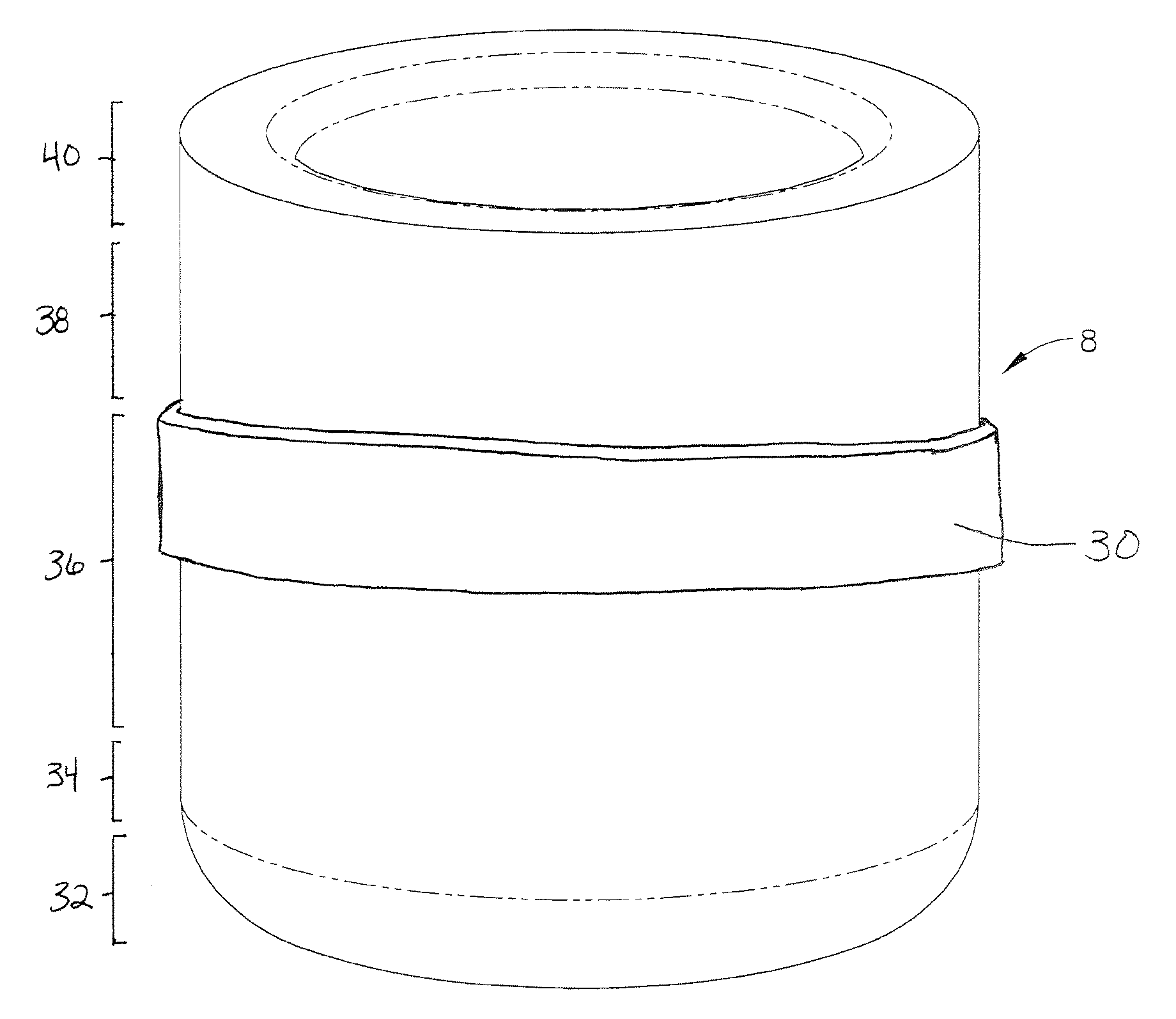
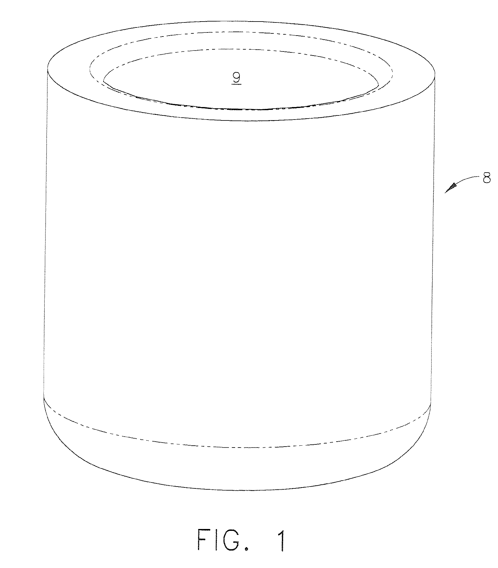
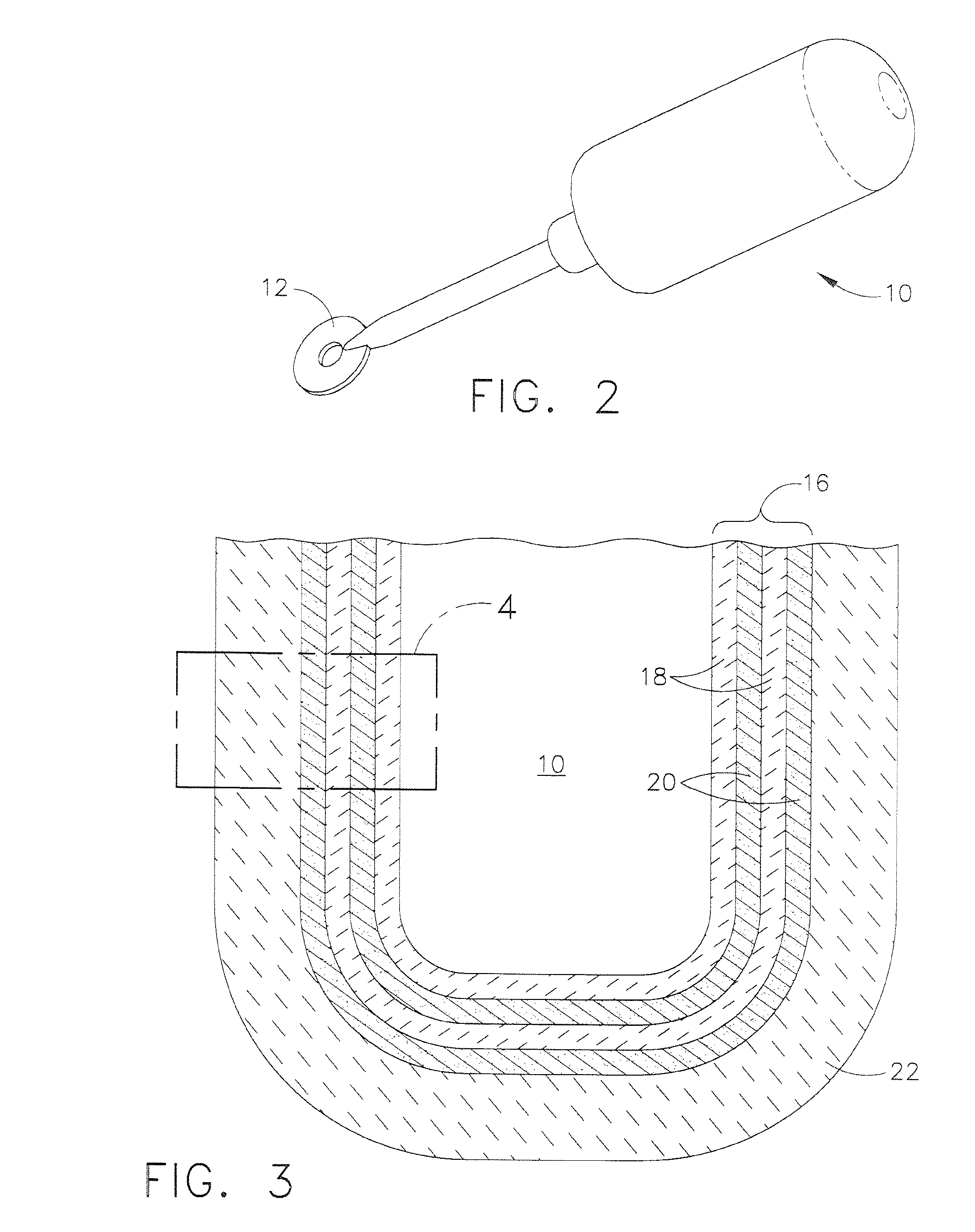
[0020]Embodiments described herein generally relate to refractory crucibles capable of managing the thermal stress generated during the casting of highly reactive titanium alloys. More specifically, embodiments described herein generally relate to refractory crucible capable of managing thermal stress and suitable for melting highly reactive alloys comprising a facecoat, a backing, and at least one retaining ring applied about at least a portion of the backing of the crucible, the retaining ring comprising a composition selected from the group consisting of conductive materials, non-conductive materials, and combinations thereof.

[0021]While embodiments herein will generally focus on crucibles suitable for melting TiAl for use in making near net shape airfoils, the description should not be limited to such. Those skilled in the art will understand that the present embodiments may be suitable for melting any titanium alloy for use in making any near net shape gas turbine component in ...


PUM

PropertyMeasurementUnit
thicknessaaaaaaaaaa
widthaaaaaaaaaa
widthaaaaaaaaaa

Abstract

Refractory crucibles capable of managing thermal stress and suitable for melting highly reactive alloys having a facecoat, a backing, and at least one retaining ring applied about at least a portion of the backing of the crucible, the retaining ring comprising a composition selected from the group consisting of conductive materials, non-conductive materials, and combinations thereof.

Description

TECHNICAL FIELD[0001]Embodiments described herein generally relate to crucibles capable of managing thermal stress. More particularly, embodiments herein generally describe refractory crucibles having at least one retaining ring for managing thermal stress, the crucible being suitable for melting highly reactive titanium alloys, such as titanium aluminide.BACKGROUND OF THE INVENTION[0002]Turbine engine designers are continuously looking for new materials with improved properties for reducing engine weight and obtaining higher engine operating temperatures. Titanium alloys, and in particular, titanium aluminide (TiAl) based alloys, possess a promising combination of low-temperature mechanical properties, such as room temperature ductility and toughness, as well as high intermediate temperature strength and creep resistance. For these reasons, TiAl-based alloys have the potential to replace nickel-based superalloys, which are currently used to make numerous turbine engine components.[...

Claims


Application Information

Patent Timeline
Patent Type & Authority Patents(United States)
IPC IPC(8): B22D45/00
CPCB22D21/005B22D41/00C22B9/003C22B34/1295F27B14/10Y02P10/25
Inventor BEWLAY, BERNARD PATRICKGIGLIOTTI, MICHAEL FRANCIS XAVIERRAHMANE, MOHAMEDKELLY, THOMAS JOSEPHWEIMER, MICHAEL JAMESSUNDARAM, SAIRAM
Owner GENERAL ELECTRIC CO
Why Eureka
Try Eureka