Device for the implantation and fixation of prosthetic valves

a technology for prosthetic heart valves and devices, applied in the field of devices for transvascular implantation and fixation of prosthetic heart valves, can solve the problems of risky surgical procedure, inability to perform procedures on patients whose hearts are already too weak, and risk of heart valve implant malalignmen

Active Publication Date: 2012-01-10
JENAVALVE TECH INC
View PDF374 Cites 156 Cited by
  • Summary
  • Abstract
  • Description
  • Claims
  • Application Information

AI Technical Summary

Benefits of technology

[0014]According to the invention, this task is solved by a device as described at the outset by the device having, in addition to the self-expanding heart valve stent with a prosthetic heart valve at its proximal end, a self-expanding positioning stent insertable into a position in the patient's aortic valve, which is configured separate from the heart valve stent, wherein the positioning stent and the heart valve stent are configured such that they each work in concert in their expanded states so that the positioning stent helps to hold the heart valve stent in a position relative the patient's heart valve predefined by the positioning stent.
[0015]The device according to the invention exhibits an entire array of substantial advantages over the prosthetic heart valves known from the prior art and described above. The two-part configuration of the device in the design of the heart valve stent and the positioning stent configured separately therefrom can, in particular, greatly increase the positioning accuracy of the prosthetic heart valve in the patient's ventricle. The positioning stent hereby primarily assumes the function of determining the position of the prosthetic heart valve in the patient's ventricle as well as the function of anchoring or fixing the prosthesis at optimum placement. In particular, the prosthetic heart valve is not on or in the positioning stent, but instead configured separately from the positioning stent on the heart valve stent This has the advantage that the dimensions of the positioning stent in its collapsed state are extremely small, which increases the stent's maneuverability.
[0016]The heart valve stent primarily serves the inventive device only as a supporting structure for the prosthetic heart valve to be implanted. This function sharing enables both the positioning stent as well as the heart valve stent to be of relatively simple configuration. What can be achieved in particular is that compared to a stent on which both a prosthetic heart valve as well as means for positioning and fixing the prosthetic heart valve are arranged, the positioning stent can be configured to exhibit only relatively small dimensions in its collapsed state. Inserting the positioning stent in the patient's artery is thus—due to the better maneuverability achieved—substantially simpler. A direct consequence of this is increased positioning accuracy for the positioning stent.

Problems solved by technology

This consequently makes the surgical procedure a risky one coupled with the associated risks for the patients and a lengthy post-operative treatment phase.
In particular, such a procedure cannot be performed on patients whose hearts are already too weak.
In the known solutions, however, there is a risk of heart valve implant malalignment.
The known solutions are also only conditionally suitable for explanting improperly or incorrectly positioned prosthetic heart valves.
Such a process is usually only possible with great effort; in particular, a further surgical procedure is required.
Among other complications, an implantation malalignment of a less than optimally positioned prosthetic heart valve can lead to, for example, leakage or valvular regurgitation, which puts a substantial burden on the ventricle.
Should, for example, a prosthetic heart valve be implanted too high above the actual heart valve plane, this can lead to occlusion of the coronary artery origination (coronaries) and thus to a fatal coronary ischemia with myocardiac infarction.
Although such a surgical introduction can be monitored and controlled, for example with fluoroscopy (Cardiac Catheterization Laboratory=CCL) or with ultrasound (Trans-esophageal Echocardiogram=TEE), oftentimes—due to the limited maneuverability of the prosthetic heart valve which is still in a collapsed state during the introduction procedure and despite being in the collapsed state is still of relatively large size—it is not possible to ensure the required positioning accuracy and especially the angular position to the prosthetic heart valve implant with the corresponding anchoring elements affixed thereto.
In particular—as a result of a possible coronary artery occlusion—an anglular misalignment to the implanted prosthetic heart valve from the optimum site of deployment can pose a threat to the respective patient.
In particular, the necessary lateral positioning accuracy and the angular position of the prosthetic heart valve can usually only be sufficiently guaranteed when the person performing the procedure has the corresponding experience.
On the other hand, explanting a previously implanted prosthetic heart valve in a minimally-invasive procedure or accordingly correcting an incorrectly positioned prosthetic heart valve has to date is only been possible with great effort, if at all.

Method used


Image

  • Device for the implantation and fixation of prosthetic valves
  • Device for the implantation and fixation of prosthetic valves
  • Device for the implantation and fixation of prosthetic valves

Examples


Embodiment Construction

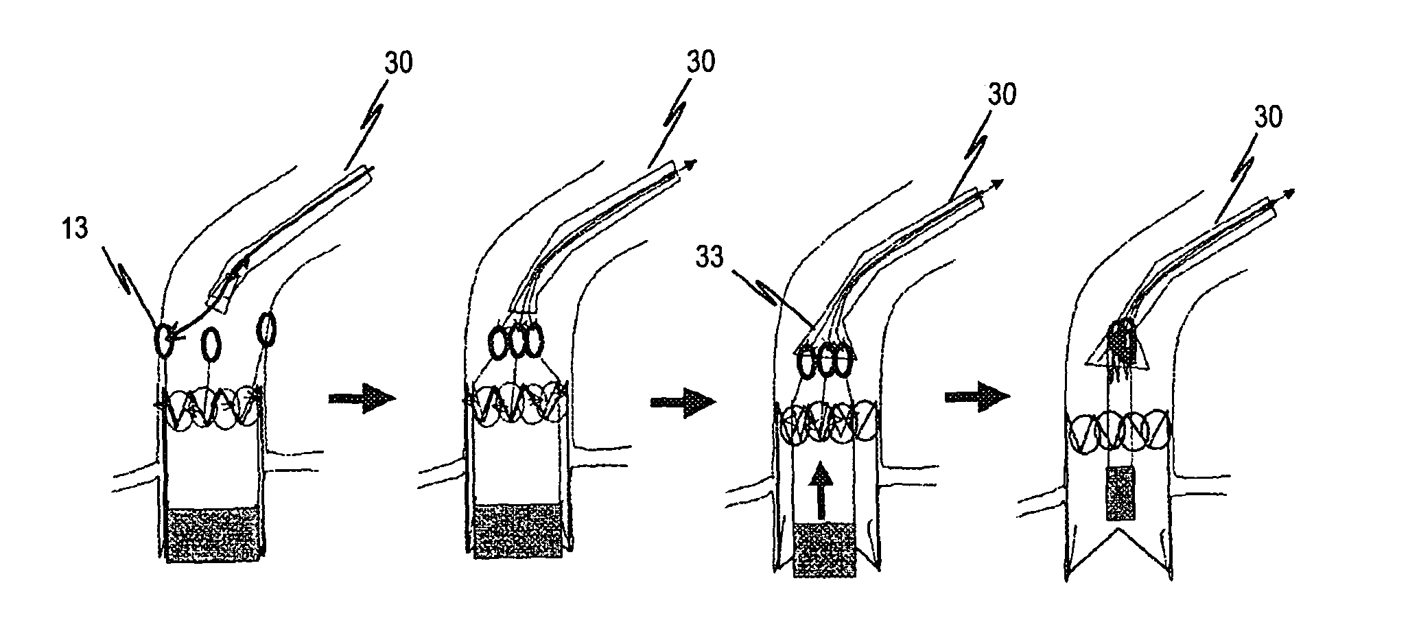
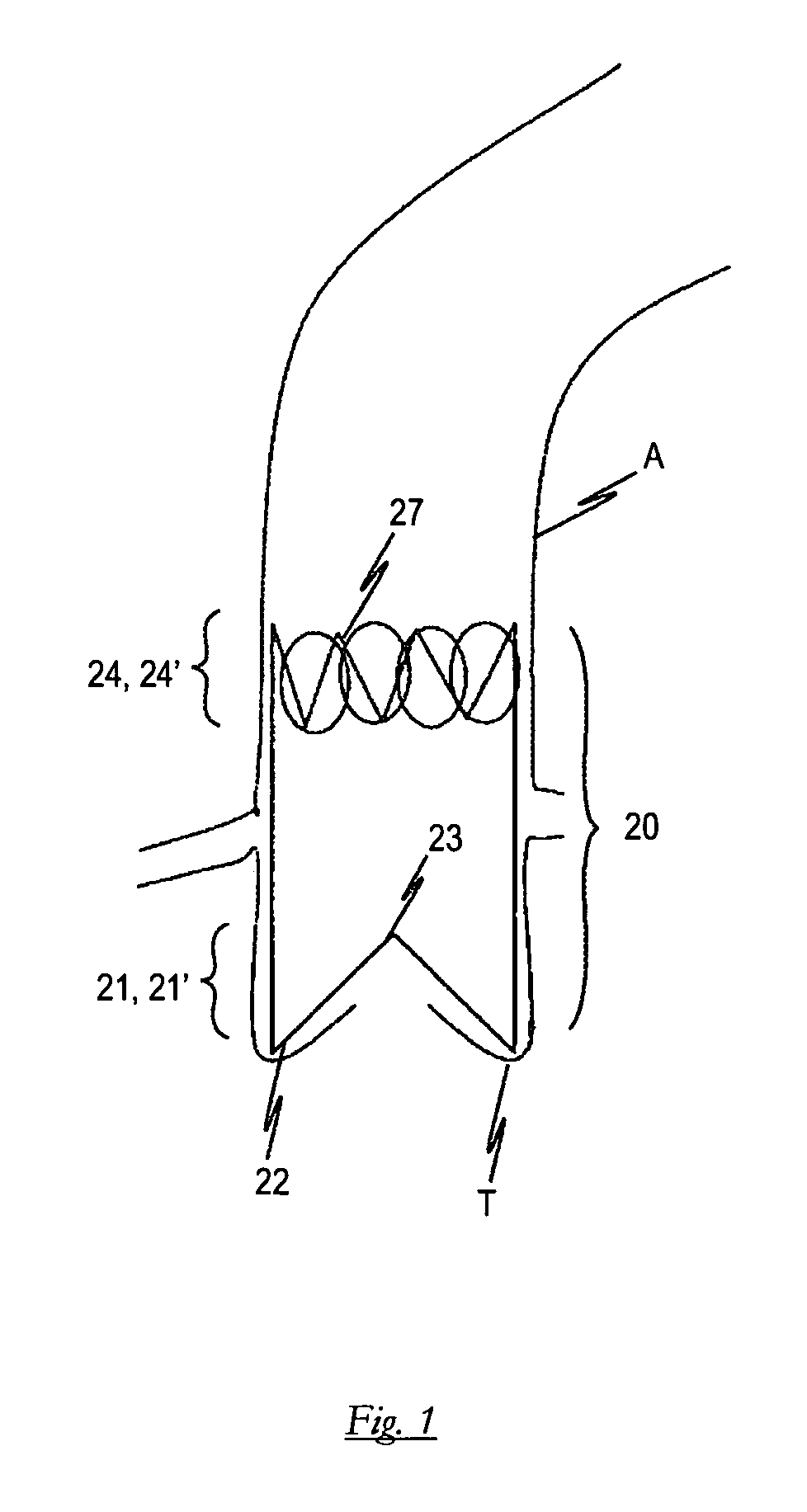
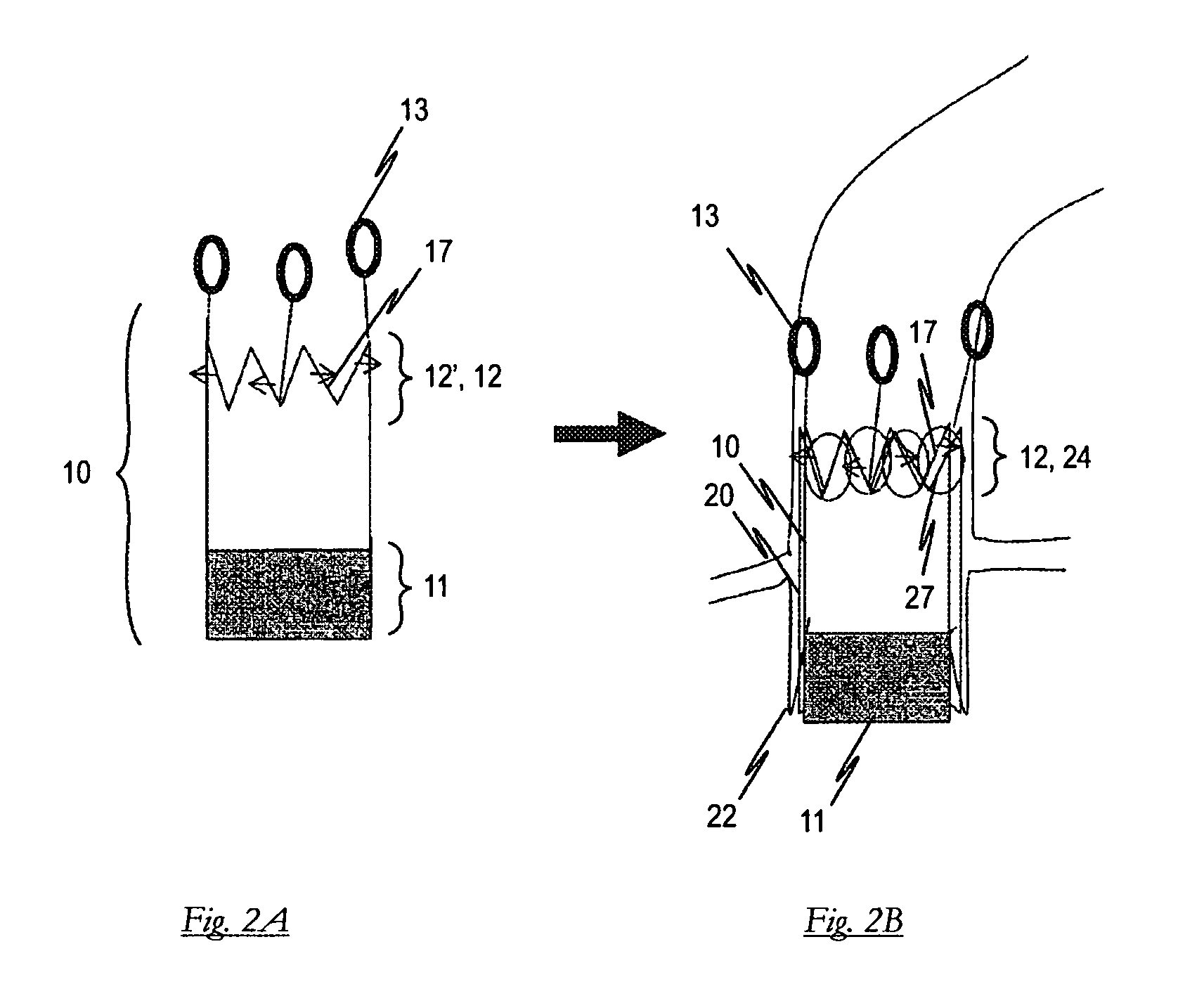
[0050]FIG. 1 shows a preferred embodiment of a positioning stent 20 for the device according to the invention in the inserted state. The positioning stent 20 is in its expanded state in the embodiment shown. As depicted, the positioning stent 20 has an anchoring segment 21′ with anchoring supports 21 at its proximal end. The anchoring supports 21 are hereby configured such that they optimize themselves into the pockets T of the old heart valve relative to axial rotation as well as horizontal position. To this end, the positioning stent 20 is supported by means of anchoring supports 21 in pockets T of the old heart valve. The anchoring supports 21 themselves are connected to docking segment 23 by means of shoulders 22. The docking segment 24′ of positioning stent 20, provided at its distal end, exhibits a plurality of engaging elements 24 which fix a heart valve stent to be implanted (not explicitly shown in FIG. 1).

[0051]The positioning stent 20 is configured as a self-expanding com...


PUM


Abstract

A device for the transvascular implantation and fixation of prosthetic heart valves having a self-expanding heart valve stent (10) with a prosthetic heart valve (11) at its proximal end is introducible into a patient's main artery. With the objective of optimizing such a device to the extent that the prosthetic heart valve (11) can be implanted into a patient in a minimally-invasive procedure, to ensure optimal positioning accuracy of the prosthesis (11) in the patient's ventricle, the device includes a self-expanding positioning stent (20) introducible into an aortic valve positioned within a patient. The positioning stent is configured separately from the heart valve stent (10) so that the two stents respectively interact in their expanded states such that the heart valve stent (10) is held by the positioning stent (20) in a position in the patient's aorta relative the heart valve predefinable by the positioning stent (20).

Description

BACKGROUND OF THE INVENTION[0001]1. Field of the Invention[0002]The present invention relates to a device for the transvascular implantation and fixation of prosthetic heart valves having a self-expanding heart valve stent with a prosthetic heart valve at its proximal end.[0003]2. Background Information[0004]A device of this type is, in principle, known to medical technology. At present, biological or mechanical valve models are available to substitute for human heart valves which are usually fixedly sewn into the bed of the heart valve during a surgical procedure through an opening in the chest after removal of the diseased heart valve. In this surgical procedure, the patient's circulation must be maintained by a heart-lung machine, whereby cardiac arrest is induced during the implantation of the prosthetic heart valve. This consequently makes the surgical procedure a risky one coupled with the associated risks for the patients and a lengthy post-operative treatment phase. In parti...

Claims


Application Information

Patent Timeline
Patent Type & Authority Patents(United States)
IPC IPC(8): A61F2/24A61F2/95
CPCA61F2/2418A61F2/2436A61F2/243A61F2/95A61F2002/9528A61F2230/0054A61F2250/006A61F2210/0014A61F2220/0025A61F2/2433A61F2/2412A61F2/82A61F2/958A61F2/2409A61F2/2427
Inventor FIGULLA, HANS-REINERFERRARI, MARKUSDAMM, CHRISTOPH
Owner JENAVALVE TECH INC
Why Eureka
Try Eureka