Lightweight ballistic armor including non-ceramic-infiltrated reaction-bonded-ceramic composite material

a composite material, non-ceramic technology, applied in the direction of ceramicware, prosthesis, other domestic articles, etc., can solve the problems of inability to stop greater projectile threats, inability to withstand projectile impact, and failure of conventional ceramic armor materials, etc., to achieve superior performance in terms of projectile impact resistan

Active Publication Date: 2012-01-31
NAVY UNITED STATES OF AMERICA SEC OF THE
View PDF55 Cites 16 Cited by
  • Summary
  • Abstract
  • Description
  • Claims
  • Application Information

AI Technical Summary

Benefits of technology

[0009]In view of the foregoing, an object of the present invention is to provide a new personnel / personal ballistic armor system that, as compared with conventional personnel / personal ballistic armor systems, affords superior performance in terms of imperviousness to projectile impact.

Problems solved by technology

Although conventional ceramic armor materials often perform satisfactorily, they (and therefore armor systems implementing them) tend to be expensive to produce.
Furthermore, conventional ceramic armor materials sometimes fail, or perform less than optimally, when impacted by a projectile.
U.S. ground troops are currently outfitted with a polymer composite helmet including aramid fibers that is capable of stopping handgun threats but is incapable of stopping greater projectile threats, such as rifles and other more powerful firearms.
In particular, body armor systems employing one or more ceramic inserts have recently seen military use, and have demonstrated varying degrees of imperviousness to greater projectile threats, but these body armor systems have been criticized for imposing excessive weight upon the wearer.
In addition, modern-day personnel / personal armor systems have generally been expensive to mass-produce.
In practice, however, items such as helmets and vests represent especially difficult applications for ceramic armor because of both weight restrictions and specialized shapes.
Ceramic armor materials of more advanced capabilities are most often prepared by hot-pressing (pressure-assisted sintering), a technique that is not suitable for preparation of an article of complex shape, such as a helmet or a vest; in general, hot-pressing is limited in terms of reduced production capacity and higher production cost.

Method used


Image

  • Lightweight ballistic armor including non-ceramic-infiltrated reaction-bonded-ceramic composite material
  • Lightweight ballistic armor including non-ceramic-infiltrated reaction-bonded-ceramic composite material
  • Lightweight ballistic armor including non-ceramic-infiltrated reaction-bonded-ceramic composite material

Examples


example 1

Glass-Infiltrated RBSN Composite Body Armor Plates

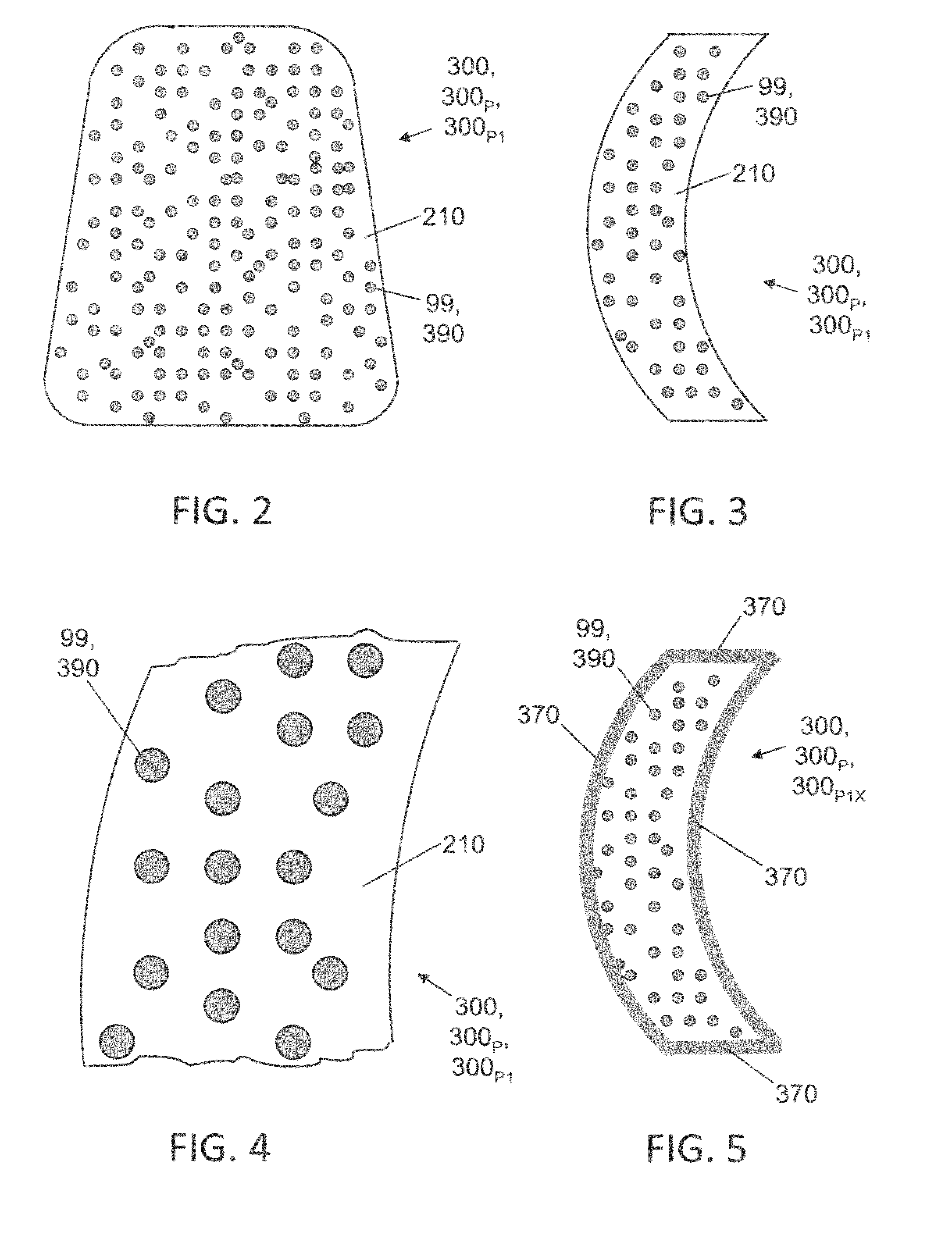
[0066]The inventive composite armor devices 300 depicted in FIG. 2 through FIG. 5 are inventive composite armor devices 300 of the homogeneously infiltrated kind. Inventive body armor plate 300P1 (shown in FIG. 2 through FIG. 4) and inventive body armor plate 300P1X (shown in FIG. 5) each include an RBSN preform phase 210 and a glass infiltrant phase 390. Glass infiltrant phase 390 at least substantially occupies the interstices (pores) defined by RBSN preform phase 210. The difference between inventive body armor plate 300P1 and inventive body armor plate 300P1X is glass infiltrant material coating 370, present in the latter.

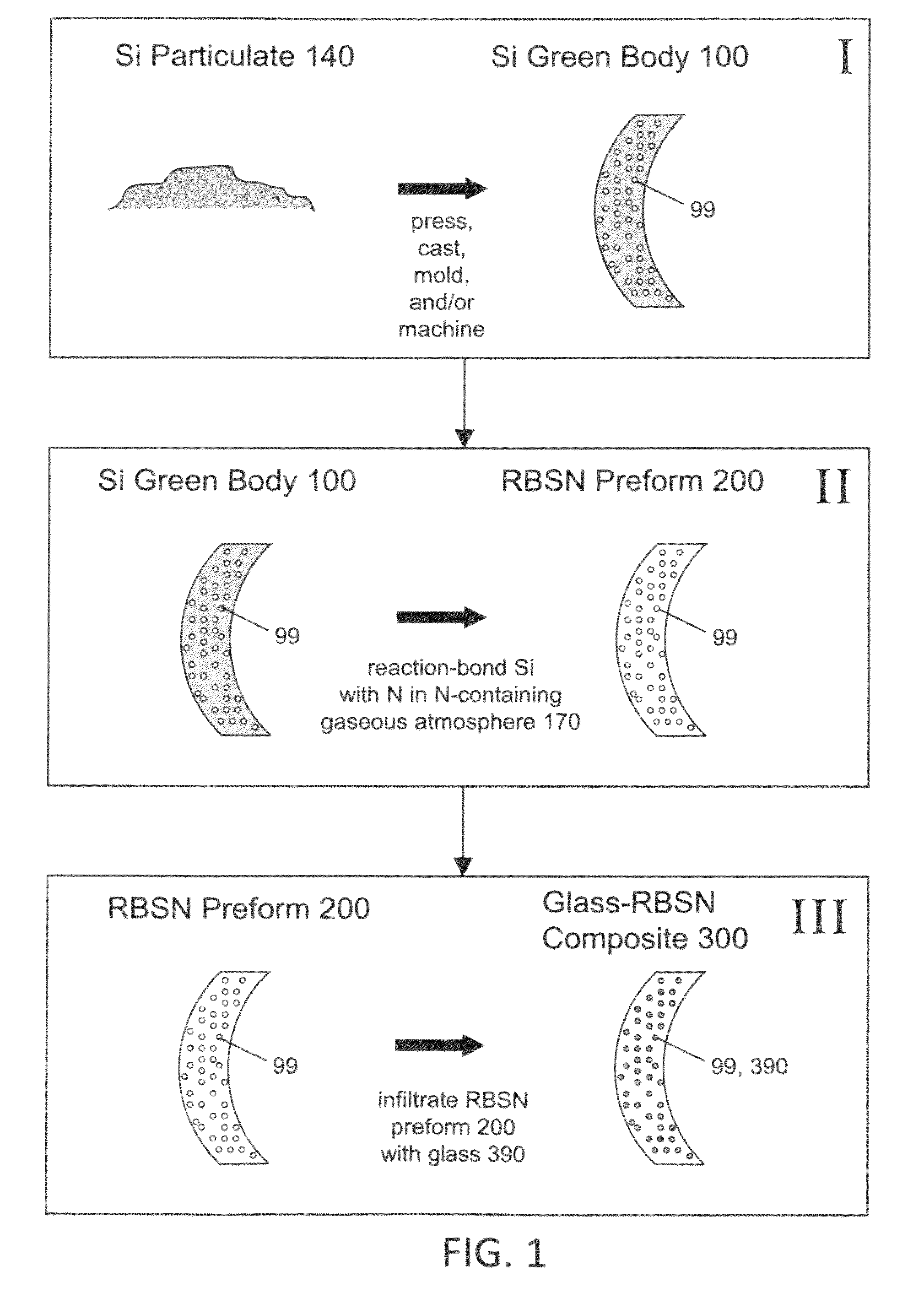
[0067]The first (green body production) stage of fabrication of inventive body armor plate 300P1 or 300P1X results in a porous silicon green body 100 having the same or approximately the same geometric shape as that shown in FIG. 2 and FIG. 3 of inventive body armor plate 300P1. The second (preform production) s...

example 2

Glass-Polymer-Infiltrated RBSN Composite Body Armor Plates

[0072]FIG. 6 through FIG. 11 can be understood to be illustrative of an inventive double-layer configuration characterized by any one of the following combinations of dissimilar composite materials: glass-infiltrated RB ceramic and polymer-infiltrated RB ceramic; glass-infiltrated RB ceramic and metal-infiltrated RB ceramic; metal-infiltrated RB ceramic and polymer-infiltrated RB ceramic.

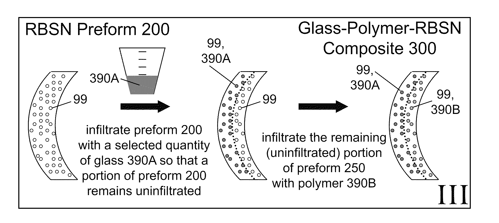
[0073]Let us assume that the inventive composite body armor device 300 depicted in FIG. 6 through FIG. 11 is an inventive double-layer composite body armor plate 300P2 having: (a) a glass-infiltrated RBSN layer 350A, with the glass phase 390A filling larger preform 200 pores 99; and, (b) a polymer-infiltrated (e.g., elastomer-infiltrated) RBSN layer 350B, with the polymer 390B filling smaller preform 200 pores 99. Although we are proceeding on this assumption by way of example, it is to be recognized that, alternatively, the inventive double-...

example 3

Glass-Metal-Polymer-Infiltrated RBSN Composite Body Armor Plates

[0088]Inventive plural-infiltrant body armor plates 300P2 (shown, by way of example, in FIG. 6 through FIG. 11) are of the inventive double-infiltrant variety. In contrast, exemplary inventive plural-infiltrant body armor plate 300P3, shown in FIG. 12, is of the inventive triple-infiltrant variety. Glass-metal-polymer-Infiltrated RBSN composite body armor plate 300 includes a glass-infiltration region 350A, a metal-infiltration (e.g., aluminum-infiltration, steel-infiltration, or titanium-infiltration) region 350C, and a polymer-infiltration (e.g., elastomer-infiltration) region 350B. The three regions of the generally flat-shaped inventive body armor plate 300P3 are aptly described as “layers.” In the inventive triple-layer body armor plate 300P3, glass-infiltration layer (region) 350A and polymer-infiltration layer (region) 350B “sandwich” therebetween the metal-infiltration layers (region) 350C.

[0089]A decreasingly “...


PUM

PropertyMeasurementUnit
porosityaaaaaaaaaa
porosityaaaaaaaaaa
porosityaaaaaaaaaa

Abstract

According to typical inventive practice, precursor particulate is pressed and/or caste and/or molded and/or machined, thereby producing a porous green body of a desired shape. A gas is brought into contact with the porous green body so that, via reaction bonding between the gas and the porous green body, the porous green body becomes a porous reaction-bonded ceramic preform, geometrically corresponding to the porous green body. One or more infiltrant materials, at least one of which is glass or polymer, is/are caused to infiltrate the pores of the RB ceramic perform. The infiltrants are selected from glass, polymer, and metal. The infiltrated preform is permitted to cool and solidify, resulting in an embodiment of an inventive non-ceramic-infiltrated reaction-bonded-ceramic structure. Because of their potential material attributes such as strength, energy dissipation, and low density, the present invention's non-ceramic-infiltrated reaction-bonded-ceramic structures are especially favorable for inclusion in personal/personnel ballistic armor systems.

Description

CROSS-REFERENCE TO RELATED APPLICATIONS[0001]This application claims the benefit of U.S. provisional patent application No. 60 / 998,459, hereby incorporated herein by reference, filing date 5 Oct. 2007, invention title “Ballistic Armor Methods, Systems and Materials,” joint inventors Curtis A. Martin, Gilbert F. Lee, Jeffrey J. Fedderly, David E. Johnson, David P. Owen, Rodney O. Peterson, Philip J. Dudt, James A. Zaykoski, Irma G. Talmy.BACKGROUND OF THE INVENTION[0002]The present invention relates to material compositions that include ceramic material, and to methods, systems, devices, and articles involving such compositions, more particularly such compositions that are relatively low in density and are otherwise suitable for use in personnel / personal ballistic armor applications.[0003]Current military armor applications include manned land vehicles, manned air vehicles (e.g., aircraft and rotorcraft), stationary structures, and persons. Other applications of armor systems are les...

Claims


Application Information

Patent Timeline
Patent Type & Authority Patents(United States)
IPC IPC(8): C04B35/00B32B3/26
CPCA61L27/427B32B3/16B32B27/18C04B41/009C04B41/48C04B41/4842C04B41/5001C04B41/5022C04B41/52C04B41/83C04B41/85C04B41/86C04B41/89F16C33/32F16C33/6696F41H5/0414C04B35/00C04B38/00C04B35/591C04B41/4523C04B41/4572C04B41/4574C04B41/51B32B2264/101B32B2264/105B32B2307/558B32B2571/02C04B2111/00353C04B2111/00836F16C2206/60Y10T428/249953C04B35/5805
Inventor MARTIN, CURTIS A.
Owner NAVY UNITED STATES OF AMERICA SEC OF THE
Why Eureka
Try Eureka