
Nano-scale bridge biosensors

a biosensor and nano-scale technology, applied in the field of nano-scale bridge biosensors, can solve the problems of changing the melting temperature, changing the thermodynamic properties, and requiring expensive fluorescent microscopes to visualize data, so as to improve the detection accuracy, reduce the cost, and improve the detection efficiency.

Active Publication Date: 2012-01-31
BOARD OF RGT THE UNIV OF TEXAS SYST
View PDF21 Cites 9 Cited by
  • Summary
  • Abstract
  • Description
  • Claims
  • Application Information

AI Technical Summary

Benefits of technology

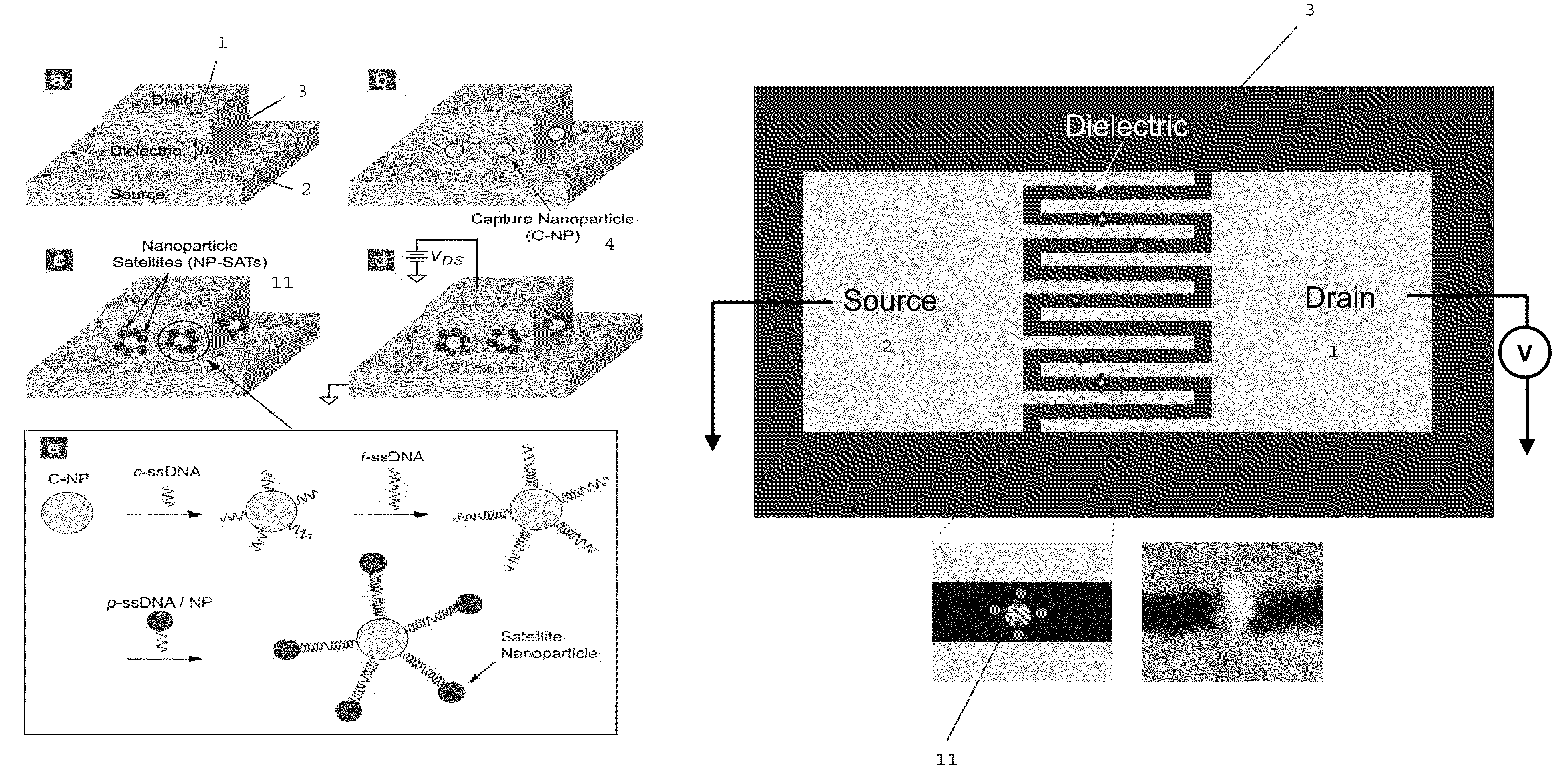
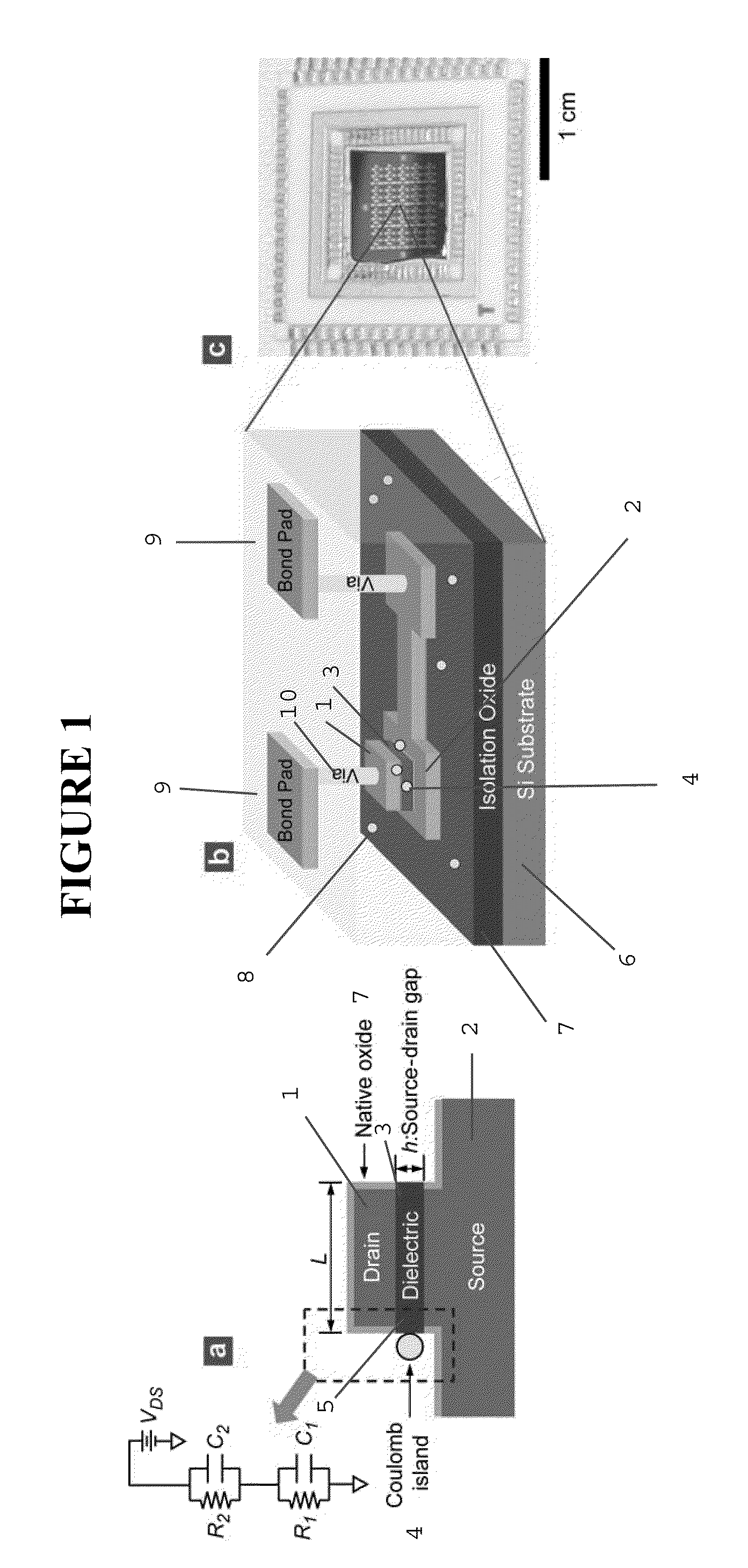
"The invention is a device that can detect small amounts of nucleic acids and amino acids with high sensitivity and without the need for external sample preparation or labeling. The device is portable, easy to use, and can be fabricated using standard semiconductor processes. It can be used in a wide range of applications, such as forensics, early disease detection, disease progression monitoring, legal matters, and immigration issues. The device uses a nanoparticle and a dielectric layer with a source and drain electrode to detect changes in the electrical current caused by the binding of specific nucleotide sequences. The device can also be used in combination with microfluidic channels and optional covers."

Problems solved by technology

However, these modifications can change the thermodynamic properties of the molecular interactions of DNA and, in some cases, unnaturally stabilize or destabilize the DNA double-strand and change the melting temperature significantly.
Additionally, expensive fluorescent microscopes are needed to visualize the data and normalization of the data to references remains problematic.
Further, the hybridization of the probe and target molecules is a diffusion-limited process requiring long-incubation times as the target molecules must travel to the arrayed probes on the surface of the chip.
While many of the silicon-based sensors can be fabricated with compact size, none of these efforts have resulted in a portable sensor with adequate performance.
The challenges range from the costly and lengthy fabrication processes to the need for external expensive measurement equipment.
The DNA hybridization detection techniques have been implemented on chips but throughput, cost, and multiplexing have not been adequately addressed.
The solid-state DNA interaction detection techniques have also required tagging of target with electrical markers, resulting in possibly altered interactions while requiring sample preparation.

Method used


Image

  • Nano-scale bridge biosensors
  • Nano-scale bridge biosensors
  • Nano-scale bridge biosensors

Examples


example 1

Formation of Self-Aligned Drain / Dielectric / Source Structure (Step a in FIG. 9)

[0493]FIG. 10 displays process steps to achieve the vertically self-aligned drain / dielectric / source structure, the starting configuration in FIG. 9(a). First, a stack of films is made on a silicon wafer using standard CMOS fabrication techniques including thermal oxidation (isolation oxide), metal evaporation (source electrode 2; Au / Cr), and PECVD 3 (silicon oxide), as shown in FIG. 10(a). On top of this film stack, the drain electrode 1 (Au) is made using photolithography, evaporation of Au / Cr, and lift-off, as shown in FIG. 10(b). The lateral dimension of the drain electrode is on the order of ˜100 μm, so that the drain electrode can be easily contacted by an electrical probe during I-V measurement. Then, using the drain electrode 1 as a hard mask, the wafer is vertically etched using reactive ion etching (RIE), producing self-aligned drain / oxide / source structure, as shown in FIG. 10(a). (The PECVD oxide...

example 2

Precise Placement of the C-NPs (Step b in FIG. 9)

[0495]The next requirement is the precise placement of C-NPs along the substantially center positions of the exposed dielectric sidewall, FIG. 9(b). To achieve this, “electrostatic funneling” method is used which, as described earlier (see FIG. 3), is proven effective for placing nanoparticles on a planar surface. To demonstrate the feasibility of accurately placing C-NPs on the sensor structure, FIG. 9(b), similar three-dimensional step structures was fabricated having differing oxide thicknesses and applied the electrostatic funneling method, FIG. 11. As is clear from the scanning electron micrograph (SEM) images, nanoparticles having differing diameters (˜200, ˜80, and ˜50 nm for FIG. 11(a), (b), and (c), respectively) were placed along the center positions of the exposed oxide sidewalls. In this demonstration, the source and drain electrodes were functionalized with negatively charged SAMs (16-mercaptohexadecanoic acid; MHA) while...

example 3

Formation of Nanoparticle Satellites Via DNA Hybridization (Step c in FIG. 9)

[0497]In the biosensor of the inventor, the presence of single-stranded oligonucleotide target (t-ssDNA) molecules leads to, through DNA hybridization (FIG. 9(e)), the formation of nanoparticle satellites (NP-SATs) around the C-NPs, FIG. 9(c). The important feature of the approach is that the DNA hybridization is carried out only on C-NPs. For this exclusive hybridization to be successful, it is essential that when migrating DNA molecules impinge on any surface except for that of C-NPs, they should not be adsorbed, but returned back into the solution so that they remain available for hybridization. Since DNA molecules are negatively charged, undesired adsorption can be prevented by passivating the silicon oxide surface using negatively-charged or non-polar molecules. There are a number of approaches for passivating the silicon oxide surface and forming NP-SATs around the C-NPs, such as those shown in FIG. 1...


PUM

PropertyMeasurementUnit
widthaaaaaaaaaa
sizeaaaaaaaaaa
sizeaaaaaaaaaa

Abstract

Devices, systems, and methods for detecting nucleic acid hybridization, including single nucleic base mutations at low concentrations, are disclosed, using capture units having nanoparticles with attached single-stranded oligonucleotides that are capable of hybridizing target oligonucleotides and reporter molecules having nanoparticles with attached single-stranded oligonucleotides, without the use of labeling or target modification.

Description

CROSS REFERENCE TO RELATED APPLICATIONS[0001]This application claims the benefit of U.S. Application No. 61 / 157,053, filed Mar. 3, 2009, the disclosure of which is incorporated herein by reference in its entirety.REFERENCE TO GOVERNMENT GRANTS[0002]Portions of the disclosure herein may have been supported, in part, by a grant from the National Science Foundation (Award No. ECCS-0925997). The United States Government may have certain rights in this application.FIELD OF THE INVENTION[0003]The invention relates generally to devices, systems, and methods for detecting nucleic acid hybridization, including single nucleic base mutations, are disclosed, using capture units having nanoparticles with attached single-stranded oligonucleotides that is capable of hybridizing target oligonucleotides and reporter molecules having nanoparticles with attached single-stranded oligonucleotides, without the use of labeling or target modification.BACKGROUND OF THE INVENTION[0004]Individual genetic muta...

Claims


Application Information

Patent Timeline
Patent Type & Authority Patents(United States)
IPC IPC(8): H01L51/10C12Q1/68G01N33/53H01L51/30C12M1/34
CPCC12Q1/6837G01N33/5438G01N2458/10C12Q2563/155C12Q2565/607Y10T436/143333
Inventor KOH, SEONG JINHUANG, HONG-WEN
Owner BOARD OF RGT THE UNIV OF TEXAS SYST
Learn More