Adsorbent structures for removal of water and fuel contaminants in engine oil

a technology of adsorbent structures and engine oil, which is applied in the direction of auxilary lubrication, lubricant mounting/connection, and separation processes, etc., can solve the problems of reducing the life of oil and engine, reducing the adsorption of contaminants, and increasing the vapor pressure of contaminants, so as to achieve easy entry of lubrication oil and extensive interaction

Inactive Publication Date: 2012-04-24
GM GLOBAL TECH OPERATIONS LLC
View PDF3 Cites 7 Cited by
  • Summary
  • Abstract
  • Description
  • Claims
  • Application Information

AI Technical Summary

Benefits of technology

[0016]The inner zeolite volume of the multi-layer zeolite particles may have particular affinity for polar contaminants such as water, methanol and ethanol. Thus, all contaminants will be accommodated in the outer layer of the multilayer particles, but the polar molecules will be drawn to the inner layer of each particle leaving the non-polar molecules occupying the outer layers. As noted previously, strongly hydrophilic behavior is observed in zeolites with low silica to alumina ratios, typically ratios of less than about 10 and preferably in ratios ranging from 1 to 3. Such a multi-layer configuration has benefit in ensuring that all classes of contaminants are sequestered in the multi-layer structure, minimizing the possibility that any one contaminant class will be disproportionately adsorbed.
[0017]Synthetic z

Problems solved by technology

At lower engine oil temperatures some of these contaminants may condense and remain in the engine lubricating oil and contribute to reduced oil life and engine damage.
As the oil temperature increases, adsorption of the contaminants becomes less favorable and some of the contaminants may be desorbed t

Method used


Image

  • Adsorbent structures for removal of water and fuel contaminants in engine oil
  • Adsorbent structures for removal of water and fuel contaminants in engine oil
  • Adsorbent structures for removal of water and fuel contaminants in engine oil

Examples


Embodiment Construction

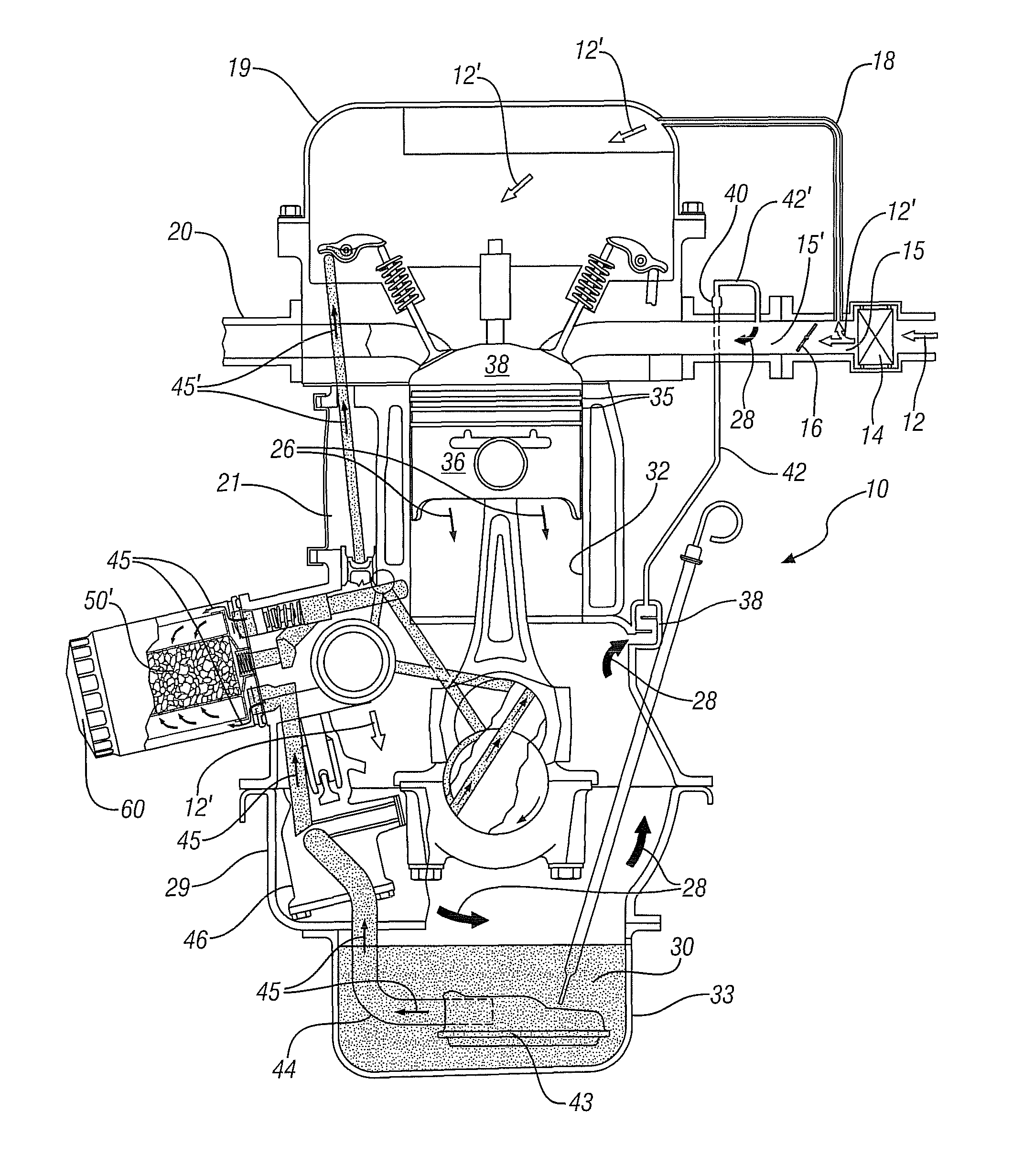
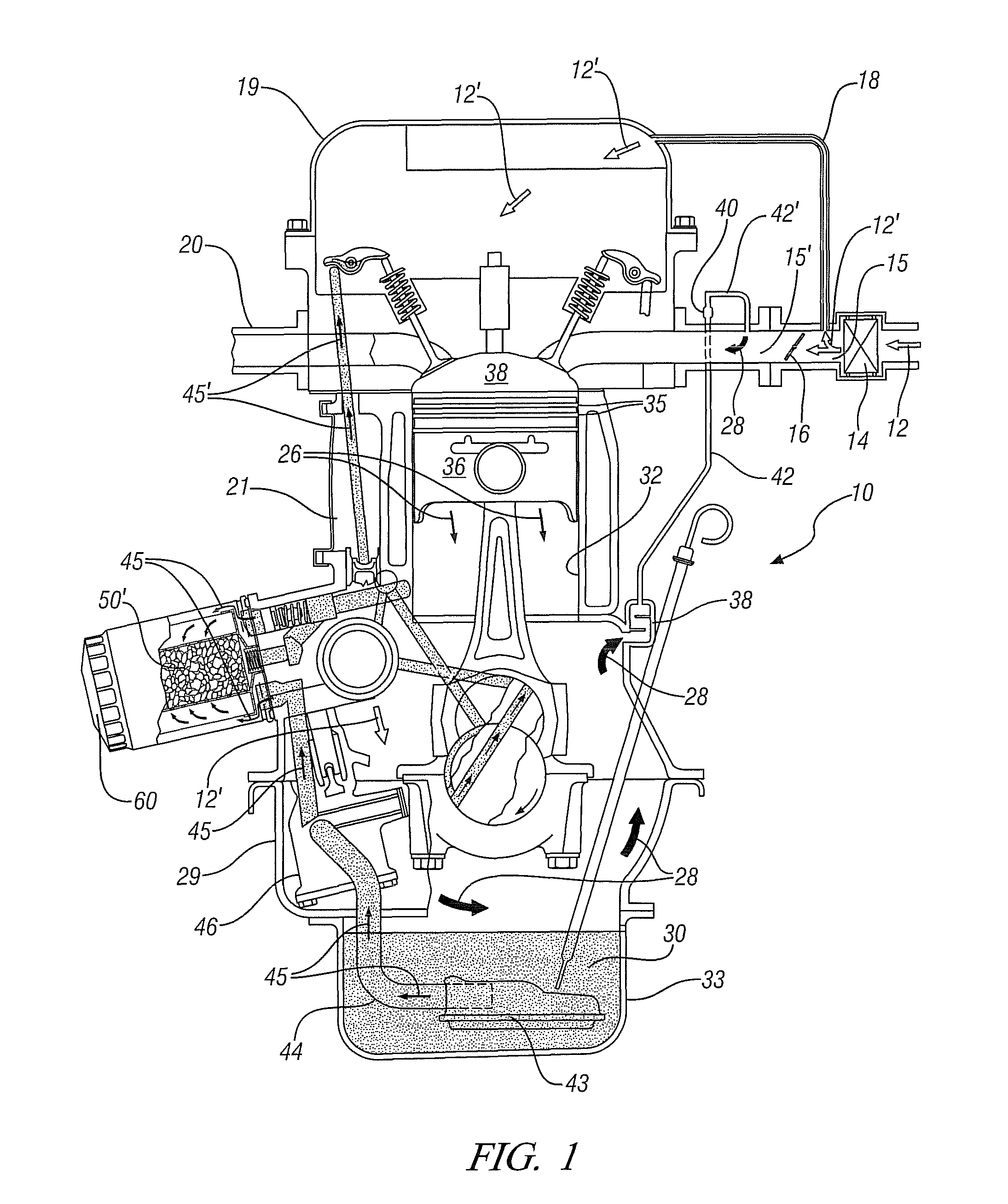
[0029]FIG. 1 shows, in cross-section, a schematic, partial-cutaway view of an automobile engine 10 with a positive crankcase ventilation (PCV) system. In operation of the PCV system, inlet air 12 is filtered by air filter 14 and enters inlet manifold 15. Before inlet air 12 encounters the constricted region of inlet manifold 15 established by throttle plate 16, a portion 12′ of the inlet air 12 is diverted into breather hose 18 and transported via the cylinder head 19 and passages 21 into crankcase 29.

[0030]In the crankcase 29 inlet air 12′ mixes with blow-by gases 26 expelled from the combustion chamber and introduced into crankcase 29 through the gap between cylinder wall 32 and the piston rings 35 of piston 36. The mixture of inlet air 12′ and blow-by gases 26, shown as crankcase gas mixture 28, circulates in crankcase 29 before navigating breather chamber 38 and passing through PCV hose 42 and PCV valve 40.

[0031]After passing through PCV valve 40, the crankcase gas mixture is im...


PUM

PropertyMeasurementUnit
Structureaaaaaaaaaa
Ratioaaaaaaaaaa

Abstract

Devices and methods for removal of condensed, blow-by contaminants with small molecular dimensions from the circulating lubricating engine oil of internal combustion engines, including automotive engines, with a positive crankcase ventilation system are disclosed. These condensable blow-by contaminants include water, alcohols and hydrocarbons with preponderantly seven or fewer carbon atoms. A macroporous structure comprising alumino-silicate particles with micro-pores is at least partially immersed in the circulating oil. The micro-pores are sized to adsorb the small, condensed, blow-by, contaminant molecules but not the larger oil molecules. The particles may be multi-layered, with an inner layer adapted for adsorption of polar molecules. Adsorption is most extensive at lower oil temperatures and decreases as the oil temperature increases. Thus at low temperatures the contaminant molecules may be adsorbed, removed from the oil and temporarily stored in the micropores. At high temperatures some of the contaminants will desorb and be re-incorporated in the oil. The desorbed contaminants will be carried with the higher temperature oil into the engine crankcase where they may vaporize and be removed by the engine positive crankcase ventilation system.

Description

TECHNICAL FIELD[0001]This invention pertains to devices and methods for temporarily adsorbing water and fuel contaminants from lubricating oil circulated in automotive internal combustion engines. More specifically, this invention pertains to the use of suitably-located crystalline particulate materials to adsorb such contaminants from relatively cold engine oil to extend oil life and to minimize potential corrosive damage to engine components. The contaminants are later released from the oil, for removal from the engine, when the engine is operating and the oil is relatively hot.BACKGROUND OF THE INVENTION[0002]Diesel, gasoline, and alcohol fueled internal combustion engines find broad application in both motor vehicles and stationary applications like motor-generators.[0003]Many such engines use hydrocarbon-based, oil lubricating systems in which the oil is pumped during engine operation from an underlying reservoir, up and over the pistons, cylinder walls, inlet and exhaust valve...

Claims


Application Information

Patent Timeline
IPC IPC(8): F02B77/00
CPCC10M175/0008C10M175/0091C10M175/02F01M1/10F01M5/00F01M11/0004F01M13/04B01J20/18B01J20/3204B01J20/3238B01J20/3293B01J20/28052F01M2001/1021F01M2011/0029F02B77/04
Inventor MORDUKHOVICH, GREGORY
Owner GM GLOBAL TECH OPERATIONS LLC
Why Eureka
Try Eureka