Solid electrolytic capacitor and its production method

a technology of solid electrolytic capacitors and production methods, which is applied in the direction of variable capacitors, fixed capacitors, fixed capacitor details, etc., can solve the problem that the anode lead is not always positioned near the center of the porous body, and achieve the effect of reducing esr

Active Publication Date: 2012-07-03
SANYO ELECTRIC CO LTD
View PDF27 Cites 3 Cited by
  • Summary
  • Abstract
  • Description
  • Claims
  • Application Information

AI Technical Summary

Benefits of technology

[0015]The conductive polymer layer in the second region including the outer peripheral part of the porous body is formed of a laminate structure of a polyethylenedioxythiophene layer and a polypyrrole layer, and therefore, this has excellent conductivity.
[0016]Accordingly, in the invention, the adhesiveness of the conductive polymer layer inside the porous body is enhanced, and the conductivity of the conductive polymer layer in the outer peripheral part of the porous body is enhanced, whereby ESR of the capacitor can be significantly reduced.
[0032]According to the production method of the invention, the solid electrolytic capacitor having a reduced ESR can be produced in a simplified manner.

Problems solved by technology

However, the anode lead is not always positioned nearly in the center inside the porous body.

Method used


Image

  • Solid electrolytic capacitor and its production method
  • Solid electrolytic capacitor and its production method
  • Solid electrolytic capacitor and its production method

Examples


first embodiment

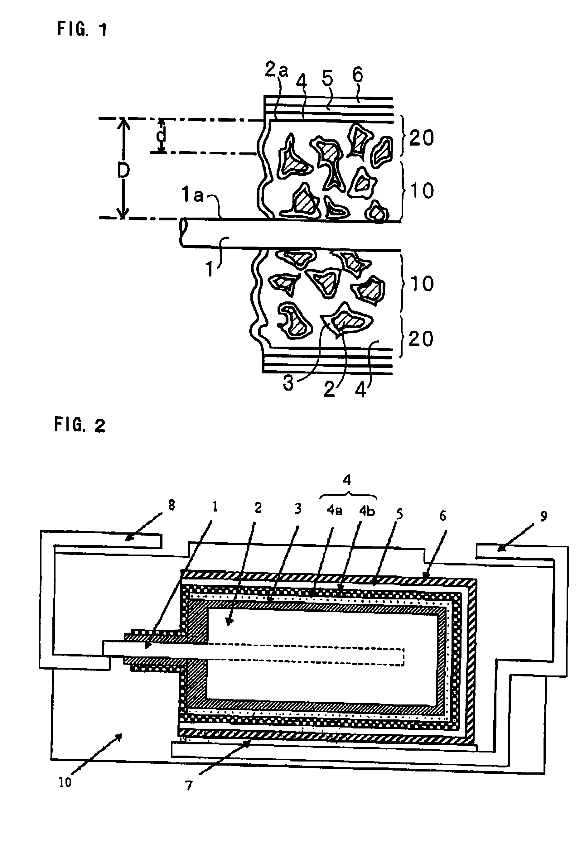
[0046]FIG. 2 is a cross-sectional view showing one embodiment of a solid electrolytic capacitor of the invention.

[0047]As shown in FIG. 2, one end of an anode lead 1 is embedded inside an anode 2. The anode 2 is formed of a porous body of a valve metal or its alloy. The porous body is formed by shaping a powder of a valve metal or its alloy and sintering it. In forming the sintered body, one end of an anode lead 1 is disposed inside the shaped body, whereby the anode lead 1 is embedded inside the anode 2.

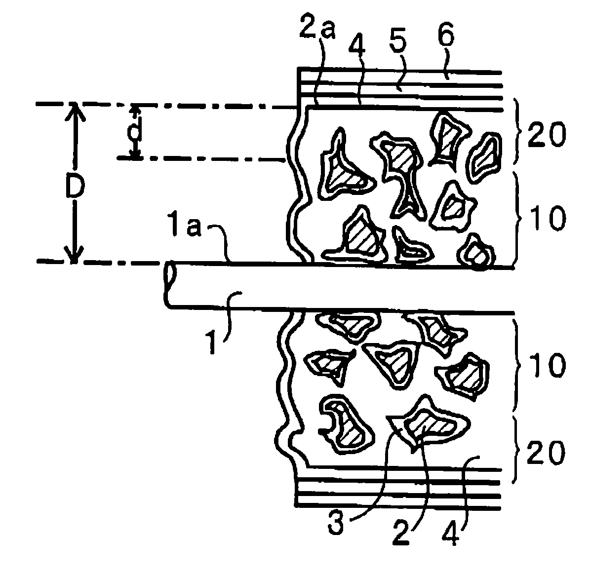
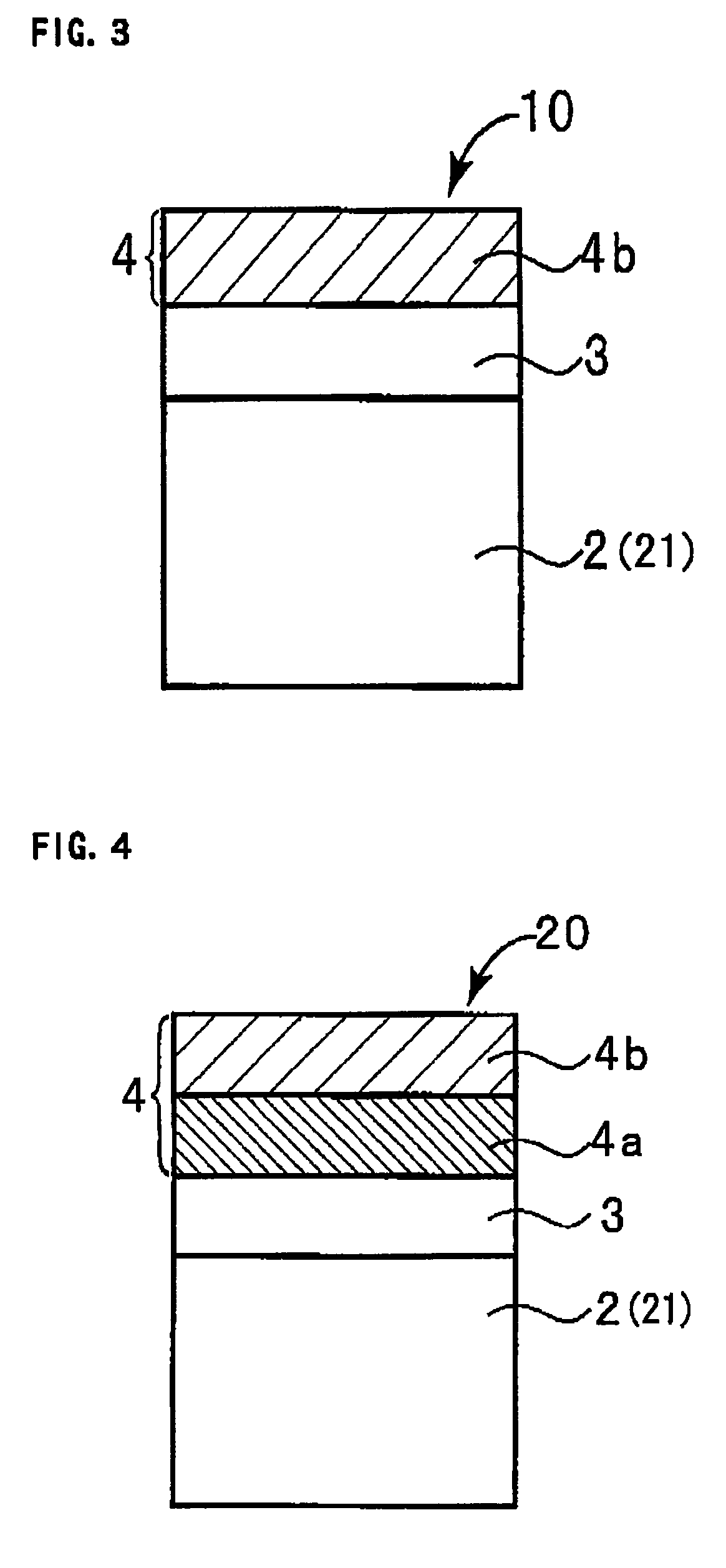
[0048]On the surface of the anode (porous body) 2, formed is a dielectric layer 3. The dielectric layer 3 is formed by anodic oxidation of the surface of the anode (porous body) 2. Not shown in FIG. 2, a dielectric layer 3 is also formed on the surface in the inside part of the anode (porous body) 2.

[0049]FIG. 1 is a schematic cross-sectional view showing the inside part of the anode (porous body) 2. As shown in FIG. 1, the anode 2 is a porous body, and therefore, a dielectric layer...

second embodiment

[0064]The this embodiment will be described with respect to only the different matters from the first embodiment in the following.

[0065]FIGS. 7A to 7E are perspective views showing a process fox producing a solid electrolytic capacity of another embodiment of the invention. FIG. 8 is a schematic cross-sectional view between A-A in FIG. 7A. FIG. 9 is a schematic cross-sectional view between A-A in FIG. 7B. FIG. 10 is a schematic cross-sectional view between A-A in FIG. 7C. FIG. 11 is a schematic cross-sectional view between A-A in FIG. 7D. FIG. 12 is a schematic cross-sectional view between A-A in FIG. 7E.

[0066]FIG. 7A shows an anode 2 with an anode lead 1 embedded therein. The anode 2 is a porous body having a rectangular shape, and the anode lead 1 is embedded therein through the center part of the side 2b thereof. As shown in FIG. 7A, the anode 2 has a flattened rectangular shape that is long in the X direction and is short in the Y direction.

[0067]The schematic cross-sectional vi...

example 1

Step 1:

[0088]First, a tantalum powder having a mean particle size of about 2 μm was sintered at about 1400° C. to form an anode of a porous sintered body with a tantalum metal lead wire embedded therein as an anode lead. The anode was processed for anodic oxidation for 10 hours at a constant voltage of 10 V in an aqueous 0.1 wt. % phosphoric acid solution kept at 40° C., thereby forming a dielectric layer of tantalum oxide on the surface in the inside part of the anode (porous body) and on the surface in the outer peripheral part thereof.

Step 2:

[0089]Next, the body formed in the step 1 was dipped in an aqueous solution of an oxidizing agent comprising 20% by weight of tertiary iron p-toluenesulfonate for 5 minutes, and then in a liquid of ethylenedioxythiophene having a purity of about 99% by weight for 10 minutes, and thereafter it was taken out, and heat-treated at 110° C. for 10 minutes to form a polyethylenedioxythiophene layer.

[0090]Next, using an ammonium persulfate solution (...


PUM

PropertyMeasurementUnit
temperatureaaaaaaaaaa
mean particle sizeaaaaaaaaaa
currentaaaaaaaaaa

Abstract

Provided is a solid electrolytic capacitor comprising an anode of a porous body formed of a valve metal or its alloy, a dielectric layer formed on the surface in the inside part of the porous body and on the surface in the outer peripheral part thereof, a conductive polymer layer formed on the dielectric layer, a cathode layer formed on the conductive polymer layer in the outer peripheral part of the porous body, and an anode lead of which one end is embedded inside the anode, wherein the conductive polymer layer in the first region which is in the inside part of the porous body and the periphery around the anode lead as the center is formed of a polypyrrole layer, and the conductive polymer layer in the second region which is the periphery around the first region is formed by laminating a polypyrrole layer on a polyethylenedioxythiophene layer.

Description

BACKGROUND OF THE INVENTION[0001]1. Field of the Invention[0002]The present invention relates to a solid electrolytic capacitor and its production method.[0003]2. Description of the Related Art[0004]With the recent tendency toward high-performance central processing unit (CPU) of personal computer (PC), it is desired to develop solid electrolytic capacitors having a reduced ESR (equivalent series resistance) in a high-frequency region. ESR depends on cathode conductivity and, in a case of multilayered cathode lamination, it depends on the contact resistance between the cathode layers.[0005]In general, a solid electrolytic capacitor comprises a porous anode formed of a valve metal or its alloy and a dielectric layer formed on the surface in the inside part or the outer peripheral part of the anode through anodic oxidation thereon, in which an electrolyte layer is provided on the dielectric layer, and a cathode is formed thereon. JP-A 4-48710 proposes formation of a conductive polymer...

Claims


Application Information

Patent Timeline
Patent Type & Authority Patents(United States)
IPC IPC(8): H01G9/00B05D5/12H01G9/04H01G4/06
CPCH01G9/025H01G9/15Y10T29/417
Inventor TAKATANI, KAZUHIROYANO, MUTSUMIUMEMOTO, TAKASHINONOUE, HIROSHI
Owner SANYO ELECTRIC CO LTD
Why Eureka
Try Eureka