Magnetic logic element with toroidal multiple magnetic films and a method of logic treatment using the same

a logic element and multilayer technology, applied in the field of magnetic logic elements with toroidal magnetic multilayers, can solve the problems of increasing the working current and power consumption of the logic cell, increasing the working current and power consumption, and reducing the shape anisotropy, so as to reduce the shape anisotropy and reduce the effect of power consumption of the logic operation method

Active Publication Date: 2012-08-07
INST OF PHYSICS - CHINESE ACAD OF SCI
View PDF12 Cites 2 Cited by
  • Summary
  • Abstract
  • Description
  • Claims
  • Application Information

AI Technical Summary

Benefits of technology

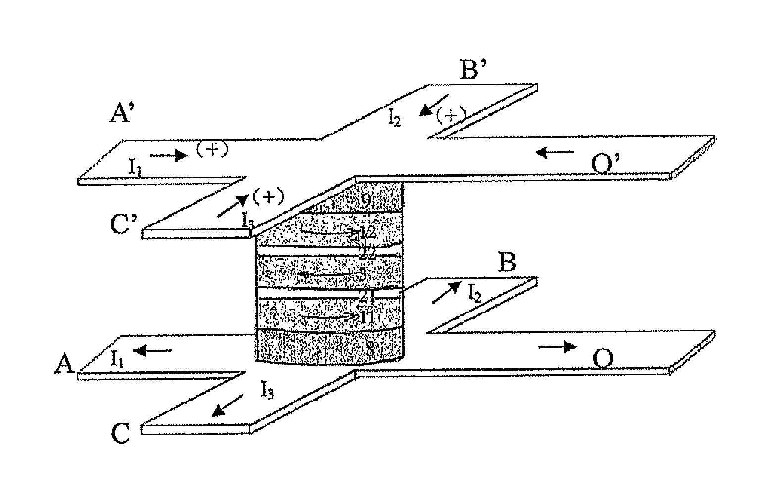
[0010]1) Logic setting: applying milli-Ampere or less than milli-Ampere of current to two input signal lines A, A′ and B, B′, or to three input signal lines A, A′, B, B′, and C, C′, intensity of current in each input signal line being identical or different, and all passing through the magnetic multilayers, allocating “0” and “1” to the magnetic multilayered cell respectively, and the reversion of the magnetic moment of various magnetic layers being achieved so as to set logic of the logic element by spin-polarized current based on the spin torque & spin-transfer switching effect and current-induced Oersted field driving;
[0014]Said metal core is made from metal materials with small resistivity, preferably, Au, Ag, Pt, Ta, W, Ti, Cu or Al. The function of the metal core is to produce a circular magnetic field by current applied from its outside, which is used to control the magnetization state of the magnetic multilayers so as to more conveniently conduct logic operation of the magnetic multilayers logic cell.
[0018]2) Logic operation: executing the logic operation by activating only two input signal lines A, A′ and B, B′, or three input signal lines A, A′, B, B′, and C, C′; only when the magnetic fields with same polarity are produced by the currents with same direction passing through the two input signal lines A, A′ and B, B′, or three input signal lines A, A′, B, B′, and C, C′, a selected initial state can be reversed, changing the output value from “1” to “0”, the reversion of the magnetic moment of various magnetic layers being achieved by spin-polarized current based on the spin torque & spin-transfer switching effect and current-induced Oersted field driving, so as to obtain multiple logic states, and the magnitude of the magnetoresistance effect of the magnetic multilayers acting as output signals.
[0038]The advantages for the magnetic logic element based on the toroidal closed magnetic multilayers provided in this invention are: the magnetic multilayered cell adopts a toroidal closed structure, which can effectively reduce high demagnetization field and shape anisotropy due to high density and small size, so as to reduce the reverse field of magnetic free layer, and further reduce current and power consumption during the logic operation. Moreover, the input line penetrates directly the magnetic multilayers, thus avoiding an adverse effect caused by non-uniform space distribution of the magnetic field, and facilitating stability of the operating performance of the logic element and life extension of the device.
[0039]The non-closed structure, such as square, rectangular and elliptic shapes are used in current techniques, which would lead to large demagnetization field and shape anisotropy under high density and small size. The closed toroidal structure adopted by this invention is able to reduce the high demagnetization field and shape anisotropy of such magnetic logic element, so as to reduce the reverse field of magnetic free layer, leading to lower current and power consumption during the logic operation. The toroidal closed structure adopted by this invention even more facilitates the direct circular magnetic driving by the spin-polarized current based on spin torque & spin-transfer switching effect and current-induced Oersted field to reverse the magnetic moment of respective magnetic layers and to realize lower power consumption during logic operation.

Problems solved by technology

However, all the input signal lines in current techniques are disposed on the magnetic multilayers, and the effective magnetic field acting on the magnetic multilayered cell is small, leading to a large operation current.
Meanwhile, non-uniform spatial distribution of the magnetic fields will bring an adverse effect.
Such a non-closed structure will bring high demagnetization fields and shape anisotropy under high density and small size, leading to increasing the reversal field of magnetic free layer, and further increasing working current and power consumption for the logic cell.
Meanwhile, the vortex magnetic domains are probably produced, resulting in an adverse effect to the uniformity and consistency of the magnetic and electrical properties of the logic element.

Method used


Image

  • Magnetic logic element with toroidal multiple magnetic films and a method of logic treatment using the same
  • Magnetic logic element with toroidal multiple magnetic films and a method of logic treatment using the same
  • Magnetic logic element with toroidal multiple magnetic films and a method of logic treatment using the same

Examples


example 1

[0051]The first structure of the magnetic logic element of this invention based on the closed toroidal magnetic multilayers will be described in detail in conjunction with the fabricating methods and diagrams as follows:

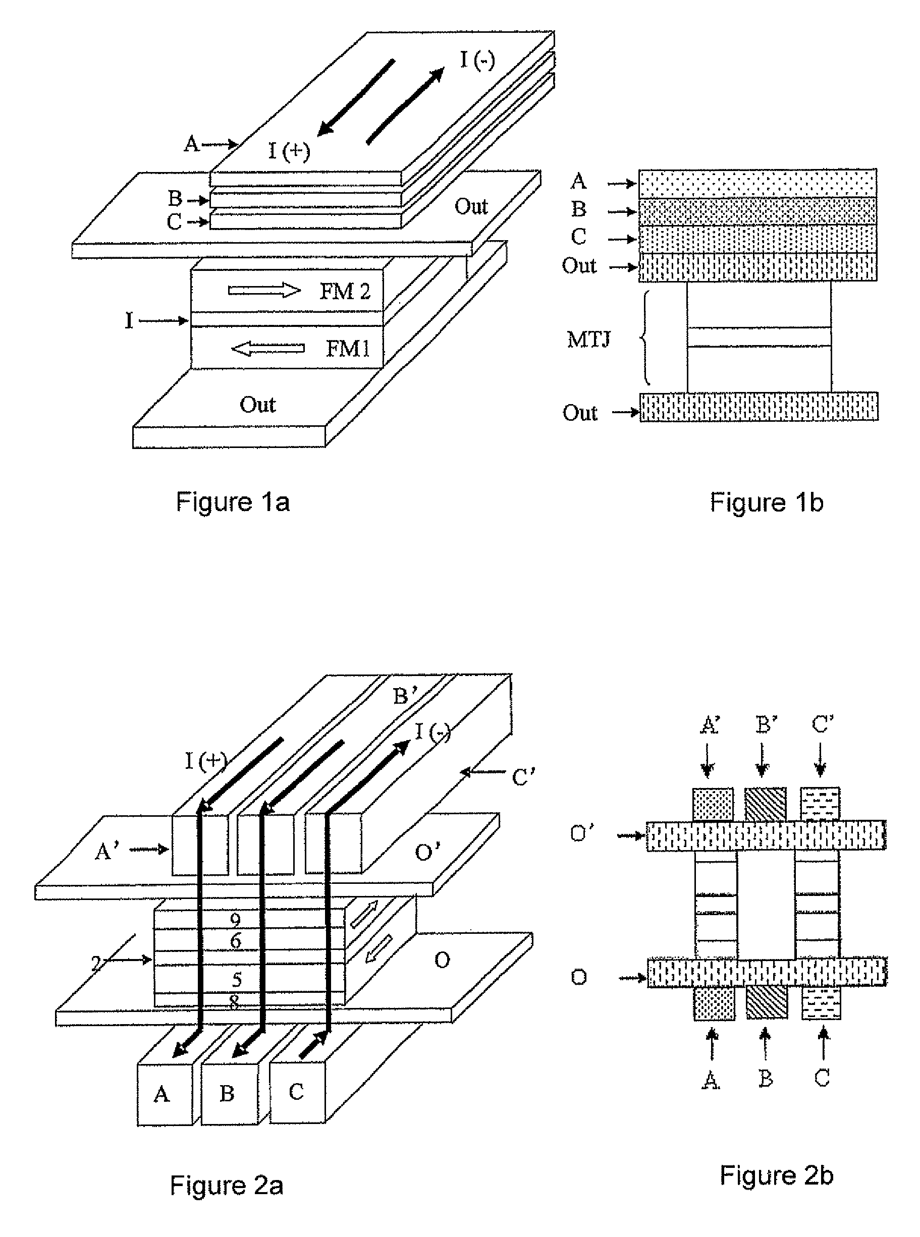
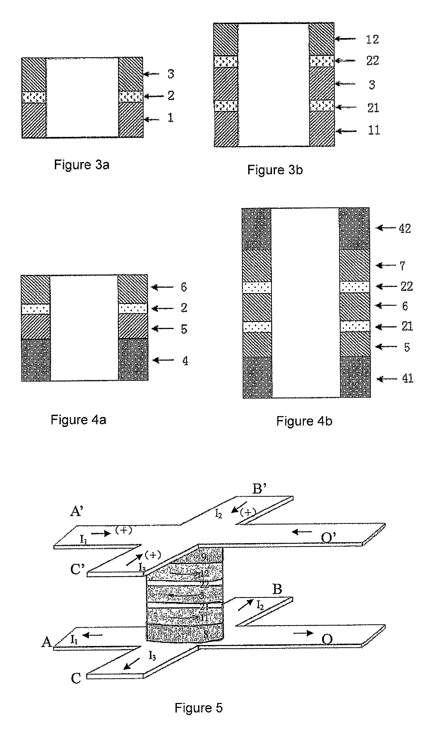
[0052]Referring to FIGS. 2a, 2b and 3a, the first magnetic logic element of this invention based on the closed toroidal magnetic multilayers is fabricated in a high vacuum magnetron sputtering equipment and by magnetron sputtering process. First, 1 mm thick SiO2 / Si substrate 13 is selected to be cleaned with conventional method. On the cleaned substrate 13, a conductive metal layer Pt of 100 nm thickness is deposited, then the up-to-date micro-fabrication process is used. That is to say, the resist is coated and pre-baked, and the substrate is exposed on the UV exposure machine according to the patterns with designed input signal lines and output signal lines, followed by development fixing and post-baking, and then the shape of the input and output signal lines is f...

example 2

[0056]The method of this example for fabricating the second magnetic logic element based on closed toroidal magnetic multilayers is the same as example 1.

[0057]Referring to FIGS. 5 and 3b, the second magnetic logic element based on closed toroidal magnetic multilayers comprises input signal lines, output signal line and closed toroidal magnetic multilayered cell. The core structure of the closed toroidal magnetic multilayered cell is: a lower hard ferromagnetic layer (HFM1) 11 of a 5 nm thick CoFe, a first intermediate layer (I1) 21 of a 2.4 nm thick Ru, a soft ferromagnetic layer (SFM) 3 of a 4 nm thick NiFeSiB, a second intermediate layer (I2) 22 of a 2.2 nm thick Au, an upper hard ferromagnetic layer (HFM2) 12 on the second intermediate layer of a 4 nm thick CoFe. The closed toroid is a round-shaped ring, with a side length of the internal ring of 200 nm, and a side length of the external ring of 300 nm.

[0058]In this solution, the core structure is made from double pseudo-spin-va...

example 3

[0059]As shown in FIGS. 6 and 4a, the specific process of the method for fabricating the third magnetic logic element based on closed toroidal magnetic multilayers is the same as example 1, comprising input signal lines, output signal line and closed toroidal magnetic multilayered cell. The core structure of the closed toroidal magnetic multilayered cell includes an anti-ferromagnetic pinning layer (AFM) 4 of 10 nm thick anti-ferromagnetic material IrMn and a pinned ferromagnetic layer (FM1) 5 of 3 nm thick CoFeB, an intermediate layer (I) 2 of 1.0 nm thick AL2O3, and a free soft ferromagnetic layer (FM2) 6 of 3 nm thick CoFeB. The closed toroid is a round-shaped ring with a size of the internal ring of 300 nm and a size of the external ring of 400 nm.

[0060]The operation mode of the magnetic logic element based on such structure is the same as example 1.


PUM

PropertyMeasurementUnit
widthaaaaaaaaaa
widthaaaaaaaaaa
lengthaaaaaaaaaa

Abstract

A magnetic logic element with toroidal magnetic multilayers (5,6,8,9). The magnetic logic element comprises a toroidal closed section which is fabricated by etching a unit of magnetic multilayers (5,6,8,9) deposited on a substrate. Optionally, the magnetic logic element may also comprise a metal core (10) in the closed toroidal section. Said magnetic multilayers (5,6,8,9) unit is arranged on the input signal lines A, B, C and an output signal line O, and then is made into a closed toroidal. Subsequently, on the toroidal magnetic multilayered unit (5,6,8,9), the input signal lines A′, B′, C′ and an output signal line O′ are fabricated by etching. This magnetic logic element can reduce the demagnetization field and the shape anisotropy effectively, leading to the decrease of the reversal field of magnetic free layer. Furthermore, this magnetic logic element has stable working performance and long operation life of the device.

Description

RELATED APPLICATIONS[0001]This application is a national stage application (under 35 U.S.C. 371) of PCT / CN2007 / 001174, filed Apr. 11, 2007.TECHNICAL FIELD[0002]This invention relates to a magnetic logic element and its operating method thereof, and in particular, to a magnetic logic element with toroidal magnetic multilayers and its method for logic process.BACKGROUND ART[0003]Since the end of 1980s when Baibich et al observed the giant magnetoresistance (GMR) effect in a magnetic multilayered system, the study of the laminated structure system composed of magnetic layer / non-magnetic layer / magnetic layer has attracted a lot of interest from scientific researchers. Such magnetic element with a giant magnetoresistance effect can not only be widely applied to the field of a magnetic sensor, magnetic record / read head, but also be developed into a radiation-resist and non-volatile magnetic random access memory (MRAM). In recent years, some research groups have proposed that magnetic memo...

Claims


Application Information

Patent Timeline
Patent Type & Authority Patents(United States)
IPC IPC(8): G11C11/02H01L29/82
CPCB82Y25/00G11C11/155G11C11/16H01F10/325H01F10/3254H01F10/3272H01L43/08H03K19/16H01F10/329H01F10/3263Y10T29/53165G11C11/1659G11C11/161G11C11/1675H10N50/10
Inventor HAN, XIUFENGZENG, ZHONGMINGHAN, YUNANJIANG, LIXIANPENG, ZILONGZHAN, WENSHAN
Owner INST OF PHYSICS - CHINESE ACAD OF SCI
Why Eureka
Try Eureka