Semiconductor device, method for producing the same, sensor and electro-optical device

a semiconductor device and electrooptical technology, applied in the direction of superconductor devices, vacuum evaporation coatings, coatings, etc., can solve the problems of insufficient properties of the semiconductor device, inability to directly form a semiconductor device, and inability to achieve the resistance reduction (high-density carrier generation) technique used for si semiconductors, etc., to achieve good device properties, low resistance, and high resistance

Active Publication Date: 2012-10-02
SAMSUNG DISPLAY CO LTD
View PDF9 Cites 31 Cited by
  • Summary
  • Abstract
  • Description
  • Claims
  • Application Information

AI Technical Summary

Benefits of technology

[0010]In order to achieve the above-described object, the present inventors focused on the fact that the sheet resistance value of an inorganic oxide film can be controlled by energy light exposure or oxidation treatment, thereby achieving the invention.
[0011]Namely, an aspect of the method for producing a semiconductor device according to the invention includes: forming a gate electrode on a substrate; forming a gate insulation film on the gate electrode; forming an inorganic oxide film on the gate insulation film, the inorganic oxide film being positioned above the gate electrode, the inorganic oxide film having a carrier density of 1019 / cm3 or more; forming a source electrode and a drain electrode connecting to the inorganic oxide film, the source electrode and the drain electrode partially covering the inorganic oxide film; and applying oxidation treatment to a region of the inorganic oxide film not covered by the source electrode and the drain electrode to reduce the carrier density of the region subjected to the oxidation treatment to 5×10¹⁶ / cm3 or less.
[0014]In the method for producing a semiconductor device according to the invention, the inorganic oxide film may be formed from an inorganic oxide film precursor which is obtained by a liquid phase method using a material liquid containing an organic solvent and at least one material selected from the group consisting of an inorganic oxide particle, an organic precursor and an organic-inorganic composite precursor. The inorganic oxide film precursor may be converted into the inorganic oxide film by applying to the inorganic oxide film precursor a treatment, such as oxidation treatment, reduction treatment, ultraviolet light treatment, vacuum treatment, heat treatment, or a combination thereof. Optionally, ultraviolet laser light may be applied to the inorganic oxide film precursor to convert the inorganic oxide film precursor into the inorganic oxide film and reduce resistance of the inorganic oxide film.
[0021]The source electrode and the drain electrode may be formed by a liquid phase method using an inorganic particle dispersion liquid containing an organic solvent and an inorganic particle being surface-coated with a dispersant, which is bound to the inorganic particle via a chemical bond breakable by the oxidation treatment, and the oxidation treatment may reduce the carrier density of the inorganic oxide film and a specific resistance value of the source electrode and the drain electrode.

Problems solved by technology

Even a material having a relatively high heat resistance, such as polyimide, has the operating temperature limit of at most about 300° C. Therefore, it is difficult to directly form a semiconductor device which necessitates a thermal process carried out at a relatively high temperature, such as a thin film transistor using silicon, on a resin substrate having low heat resistance.
Therefore, depending on the solid state properties of the formed thin film, the off current increases if the semiconductor device is directly formed, and it is not possible to obtain sufficient properties of the semiconductor device.
However, for the oxide semiconductors, a resistance reduction (high-density carrier generation) technique, such as doping (impurity implantation) used for Si semiconductors, has not been established.
Therefore, it is difficult to produce a semiconductor device by reducing the resistance only at the source region and the drain region to reduce the contact resistance between these regions and electrodes.
Therefore, it is impossible to provide good contact between these electrodes and these regions.

Method used


Image

  • Semiconductor device, method for producing the same, sensor and electro-optical device
  • Semiconductor device, method for producing the same, sensor and electro-optical device
  • Semiconductor device, method for producing the same, sensor and electro-optical device

Examples


first embodiment

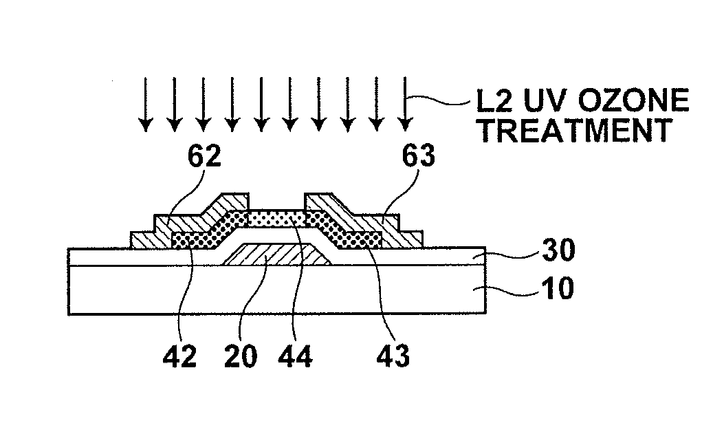
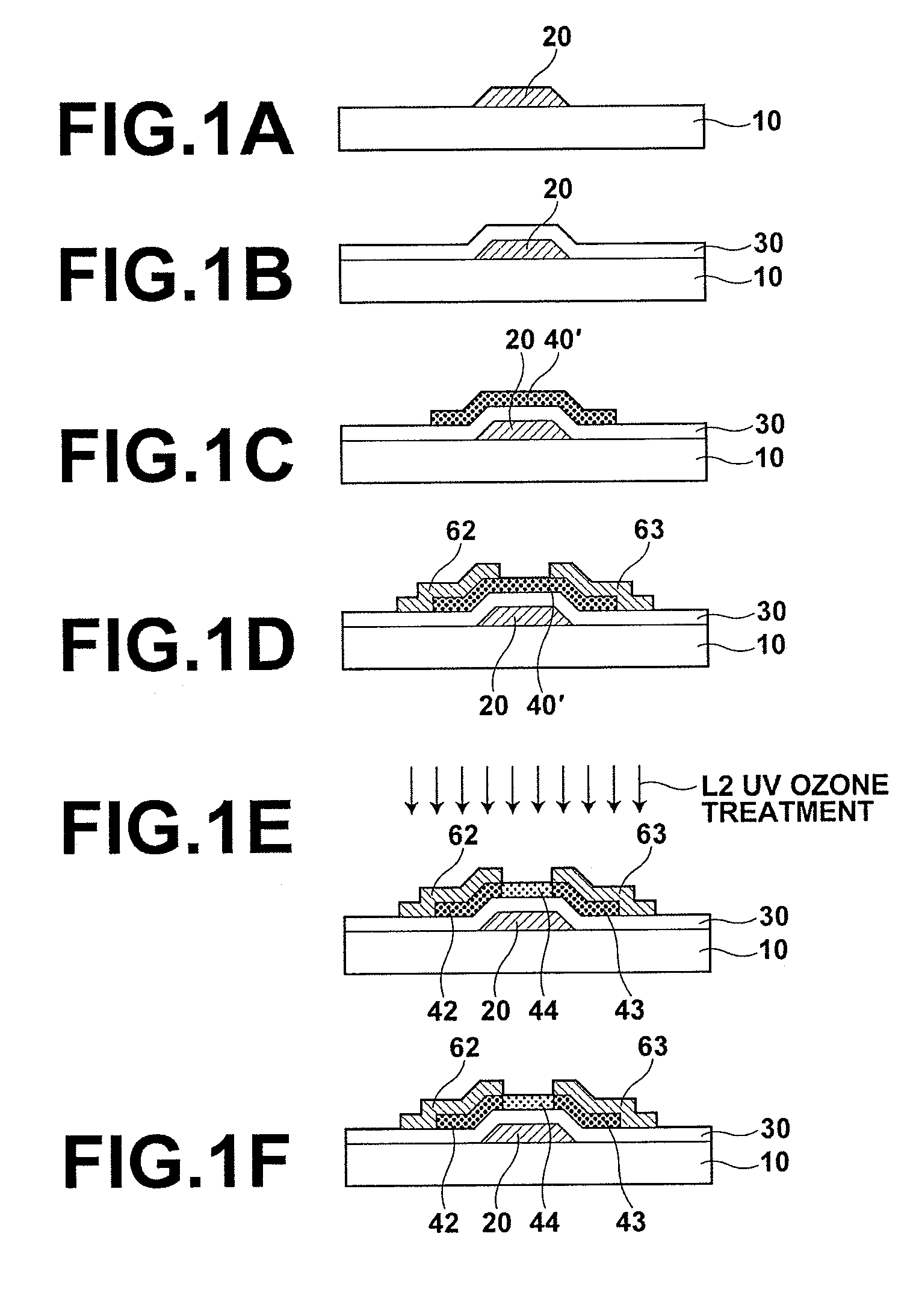
[0036]FIGS. 1A-1F are schematic sectional views illustrating the production flow of a method for producing a semiconductor device according to a first embodiment. FIG. 1F illustrates the semiconductor device produced by the production method according to this embodiment.

[0037]As shown in the drawings, in the method for producing a semiconductor device according to this embodiment, a patterned gate electrode 20 is formed on a substrate 10 (FIG. 1A), a gate insulation film 30 is formed (FIG. 1B), and an inorganic oxide film 40′ having a carrier density of 1019 / cm3 or more is formed through a dry process on the gate insulation film 30 so that the inorganic oxide film 40′ is positioned above the gate electrode 20 (FIG. 1C). Thereafter, a source electrode 62 and a drain electrode 63 are formed through a dry process to partially cover the inorganic oxide film 40′ (FIG. 1D), and oxidation treatment (in FIG. 1E, UV ozone treatment using ultraviolet light L2 is shown as an example) is applie...

second embodiment

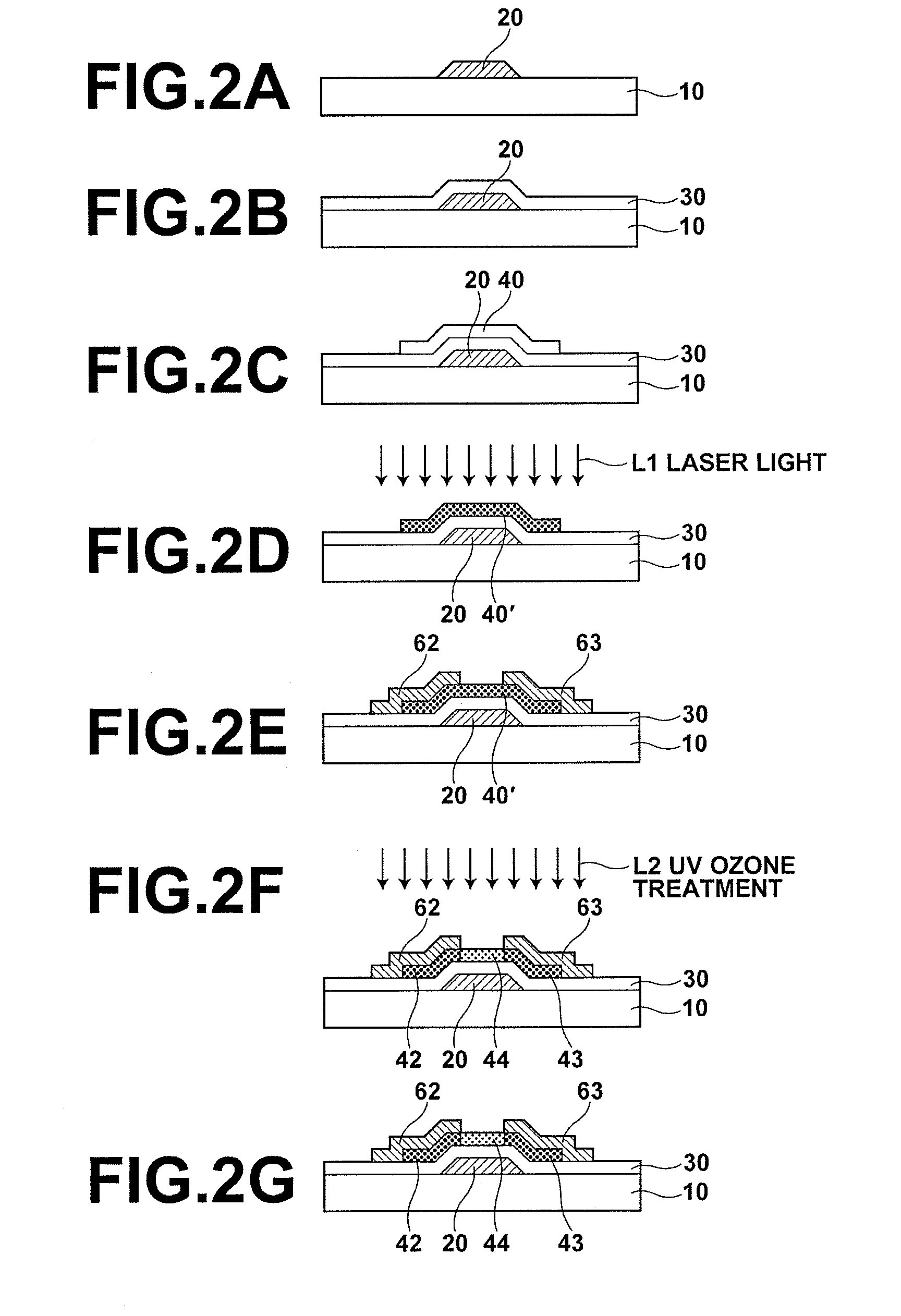
[0057]FIGS. 2A-2G are schematic sectional views illustrating the production flow of a method for producing a semiconductor device according to a second embodiment. FIG. 2G illustrates the semiconductor device produced by the production method according to this embodiment.

[0058]The method for producing a semiconductor device of this embodiment differs from the method of first embodiment in that, in the second embodiment, the inorganic oxide film 40′ is formed by a liquid phase method. The other features are the same as the first embodiment, and therefore, description of the same features as the first embodiment shown in FIG. 1 is omitted unless it is necessary.

[0059]As shown in the drawing, in the method for producing a semiconductor device according to this embodiment, the patterned gate electrode 20 is formed on the substrate 10 (FIG. 2A), the gate insulation film 30 is formed (FIG. 2B), an inorganic oxide film precursor 40 is formed through a liquid phase method on the gate insula...

third embodiment

[0085]FIGS. 3A-3G are schematic sectional views illustrating the production flow of a method for producing a semiconductor device according to a third embodiment. FIG. 3G illustrates the semiconductor device produced by the production method according to this embodiment.

[0086]The method for producing a semiconductor device of this embodiment differs from the method of the second embodiment in that the source electrode 62 and the drain electrode 63 are formed using a liquid phase method, in stead of the dry process. The other features are the same as the second embodiment, and therefore, description of the same features as the second embodiment shown in FIGS. 2A-2G is omitted unless it is necessary.

[0087]As shown in the drawing, in the method for producing a semiconductor device according to this embodiment, the patterned gate electrode 20 is formed on the substrate 10 (FIG. 3A), the gate insulation film 30 is formed (FIG. 3B), the inorganic oxide film precursor 40 is formed through ...


PUM

PropertyMeasurementUnit
operating temperatureaaaaaaaaaa
heat resistanceaaaaaaaaaa
thicknessaaaaaaaaaa

Abstract

A gate electrode, a gate insulation film and an inorganic oxide film are formed in this order on a substrate, and a source electrode and a drain electrode are formed to partially cover the inorganic oxide film. Then, oxidation treatment is applied to reduce the carrier density at a region of the inorganic oxide film which is not covered by the electrodes and is used as a channel region of a semiconductor device.

Description

BACKGROUND OF THE INVENTION[0001]1. Field of the Invention[0002]The present invention relates to a semiconductor device, a method for producing the semiconductor device, a sensor and an electro-optical device. More particularly, the present invention relates to a semiconductor device and a method for producing the semiconductor device, which utilize resistance control of an inorganic oxide film through energy light exposure and oxidation treatment, as well as a sensor and an electro-optical device employing the semiconductor device.[0003]2. Description of the Related Art[0004]In recent years, various types of flexible devices are receiving attention. The flexible devices have various uses, such as electronic paper and flexible displays. The structure of a flexible device basically includes a crystalline semiconductor or a metal film patterned on a flexible substrate, such as a resin substrate. Since the flexible substrates have a lower heat resistance than that of inorganic substrat...

Claims


Application Information

Patent Timeline
Patent Type & Authority Patents(United States)
IPC IPC(8): H01L51/40C23C14/30B05D5/12H01L21/44H01L21/00
CPCH01L21/28194H01L29/7869
Inventor TANAKA, ATSUSHIUMEDA, KENICHIHIGASHI, KOHEINANGU, MAKI
Owner SAMSUNG DISPLAY CO LTD
Why Eureka
Try Eureka