

High strength electrodeposited suspension conductors
- Summary
- Abstract
- Description
- Claims
- Application Information
AI Technical Summary
Benefits of technology
Problems solved by technology
Method used
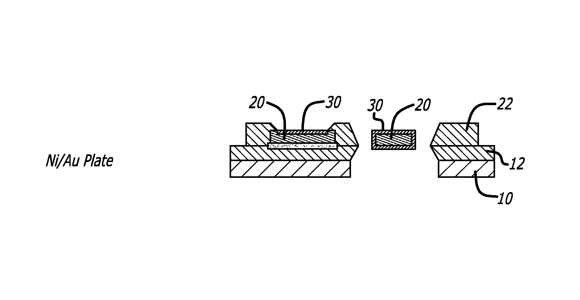
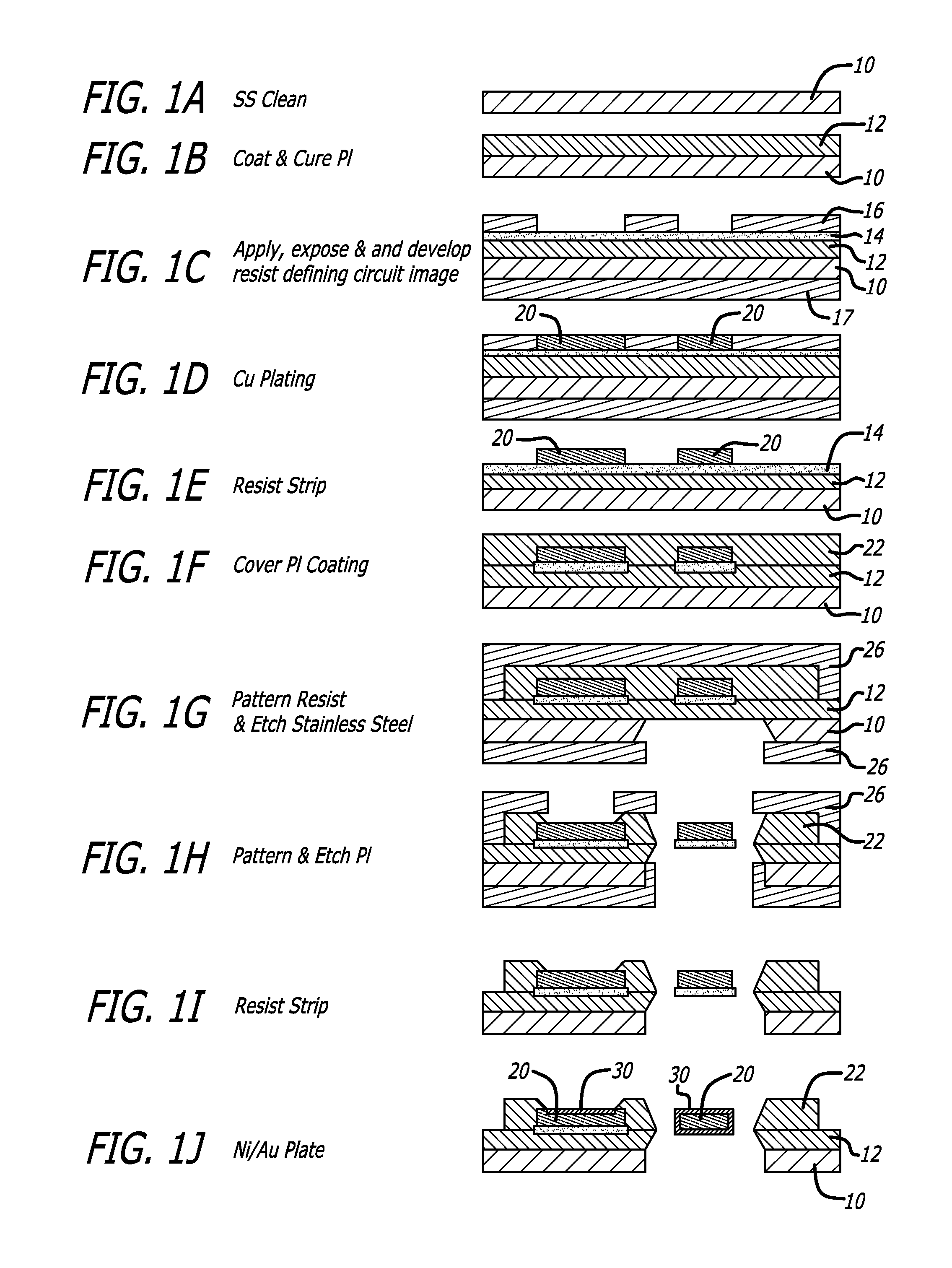
Image

Examples
example 1
[0044]In the preferred embodiment an electrolytic bath containing the following principal constituents is used, and electrodeposition took place under the following conditions:
[0045]
Common NameChemical FormulaConcentrationCopper SulfateCuS04•5H2067 g / l(pentahydrous)Copper SulfateCuS04225 g / l(anhydrous)Hydrochloric AcidHCl0.154 m / lPC-6713 ml / lStannous Sulfate SnSO44 g / l(tin ions)Ferrous SulfateFeSO440 g / l(iron ions)Current Density: 12 ASD (peak) (ON), 25% duty cycle, 500 Hz (0.5 ms ON, 1.5 ms OFF)
[0046]Acid copper plating is well known in the art, as exemplified by Metal Finishing, 55th Guidebook Directory (Metals and Plastics Publications Inc., Hackensack, N.J., 1987), pp. 212-215 which is hereby incorporated by reference in its entirety for its teachings of electrolytic copper plating baths and processes. The stannous sulfate, which can be difficult to get into solution, was mixed with a magnetic stirrer in a separate solution for seven days. The undissolved white stannous sulfate ...
example 2
[0052]Electrodeposited copper was prepared using the following electrolytic bath:
[0053]
Common NameChemical FormulaConcentrationCopper SulfateCuS04•5H20283-334 g / lSulfuric AcidH2S04110-200 g / lPolyether0.01-1.10 g / lStannous Sulfate SnSO40.5-1.0 g / l(tin ions)Ferrous SulfateFeSO40.5-5.0 g / l(iron ions)Chloride ionsCl−≦0.1 mg / lTemperature: 20-25° C.Current Density: 15-45 ASFCurrent Pulsing: 25-75%, 500 Hz
This is the same bath chemical constituents as taught by Sakai et al. in U.S. Pat. No. 5,958,209 to plate a foil with high mechanical properties for etching that does not significantly degrade when subject to high temperature (180° C.). However, the bath was used at a different temperature and at a much lower current density than suggested by Sakai, and with current pulsing.
[0054]Unlike methods of manufacturing rolled copper foil in which the anode can be shaped to minimize the preferential plating to high current density areas (point source), and the edges of the electrodeposited foil ca...
example 3
[0055]A high throw copper plating solution with the following make up, operated at a bath temperature of approximately 20-25° C., will yield satisfactory results:
[0056]
Common NameChemical FormulaConcentrationCopper SulfateCuS04•5H2060-100 g / lSulfuric AcidH2S04170-220 g / lStannous Sulfate SnSO40.5-1.0 g / l(tin ions)Ferrous SulfateFeSO40.5-5.0 g / l(iron ions)Chloride ionsCl−ppmBrightener PC GleamTemperature: 20-25° C.Current Density: 15-45 ASFCurrent Pulsing: 25-75%, 500 Hz
The preferred 2-component commercially available brightener is Copper Gleam distributed by LeaRonel Inc. of Freeport, N.Y.
PUM
| Property | Measurement | Unit |
|---|---|---|
| Temperature | aaaaa | aaaaa |
| Temperature | aaaaa | aaaaa |
| Temperature | aaaaa | aaaaa |
Abstract
Description
Claims
Application Information