Low-temperature, converging, reactive gas source and method of use

Active Publication Date: 2012-12-11
SURFX TECH
View PDF21 Cites 74 Cited by
  • Summary
  • Abstract
  • Description
  • Claims
  • Application Information

AI Technical Summary

Benefits of technology

[0021]Similarly, a typical method of surface treatment includes the steps of flowing a gas through an inlet of a first electrode, flowing the gas along a gap between the first electrode and a second electrode disposed proximate to the first electrode such that the gas flows from a plurality of directions to converge and flow through an outlet in the second electrode, and applying high frequency electrical power between the first electrode and the second electrode to generate a plasma within the gas flow such that a reactive gas of the plasma emerges at the outlet and impinges on a workpiece placed downstream. Typically, the surface treatment is carried out at substantially atmospheric pressures and/or at temperatures below 500° C. The method may include the steps of feeding one o

Problems solved by technology

Therefore, this device is for the most part restricted to treating plastic film or fabric that is continuously passed through the plasma in a roll-to-roll format.
Hollow cathode discharges are mostly used as light sources and processing materials with these devices has been limited.
The disadvantage of these designs is that the plasma beam is produced as a small spot.
In addition, the co

Method used


Image

  • Low-temperature, converging, reactive gas source and method of use
  • Low-temperature, converging, reactive gas source and method of use
  • Low-temperature, converging, reactive gas source and method of use

Examples


example 1

Surface Activation

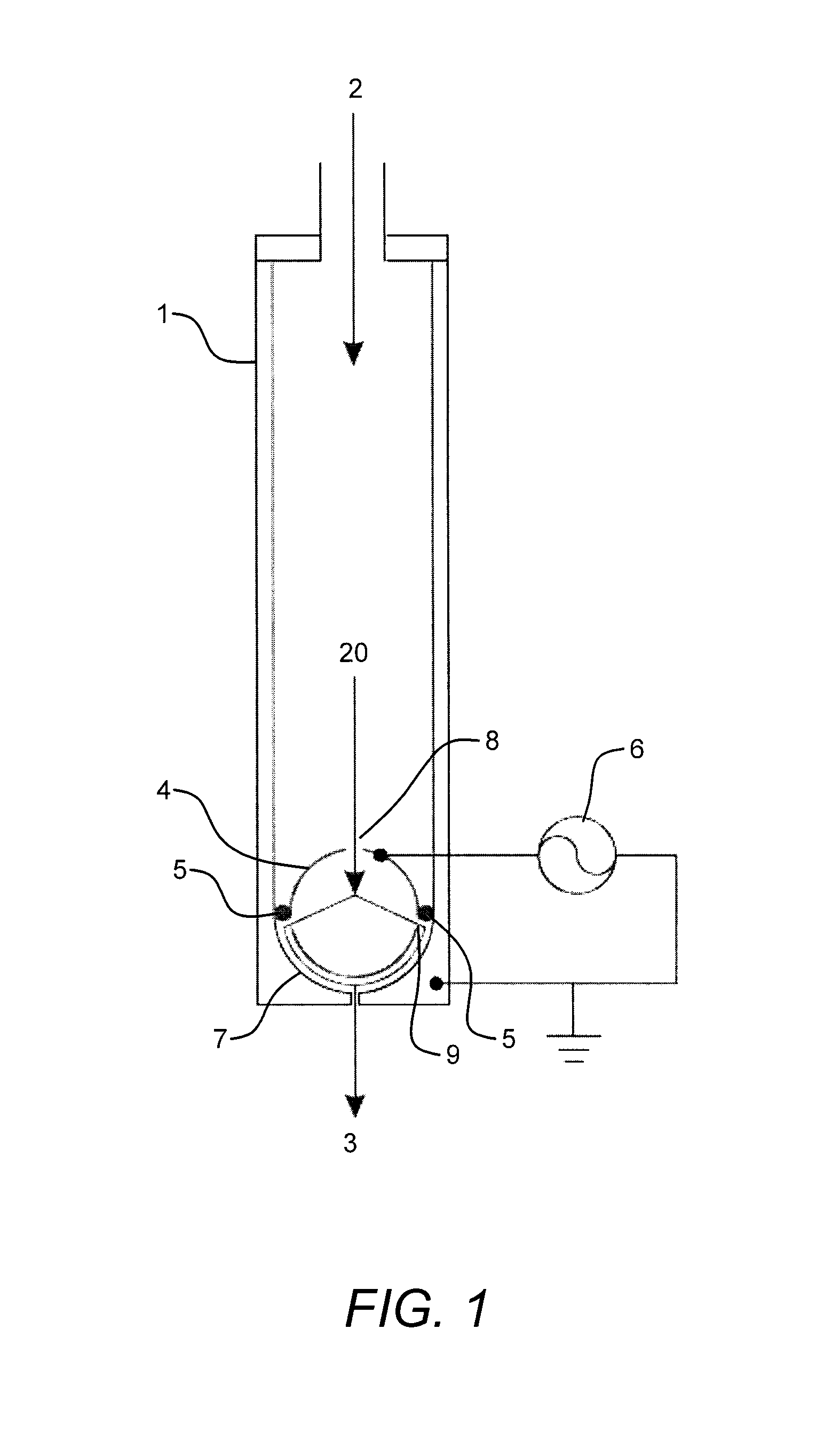
[0061]The apparatus shown in FIG. 1 was used to activate the surface of plastic materials. A mixture of helium at 30.0 L / min and oxygen at 1.5 L / min was fed into the rectangular housing. The plasma was struck in the device by applying radio frequency power at 250 W and 27.12 MHz. The plastic was placed 1.0 cm downstream of the outlet of the housing, and the housing was scanned over the sample at a constant rate. Before and after plasma treatment, the surface energy of each material was measured with ACCUDYNE Test markers. The results of these experiments are shown in TABLE 1.

[0062]

TABLE 1Surface activation of plastic samples.Surface energy (dyne / cm)Scan rateExposureSubstrateInitialFinal(cm / s)time (s)Polypropylene3270+1.30.06Nylon4670+2.50.03Silicone rubber3070+1.30.06ABS4270+1.30.06HDPE3870+0.60.13

[0063]A surface energy greater than 70 dyne / cm means that the sample surface is hydrophilic, and that a water droplet will spread out flat on it. On polypropylene, silico...

example 2

Etching KAPTON

[0064]The present invention may be used to etch materials. For example KAPTON may be etched by exposure to the oxygen plasma, whereas silicate glass and tantalum may be etched by exposure to a fluorine and oxygen plasma. The apparatus presented in FIG. 1 was used to etch KAPTON films, 50 microns thick, at the following conditions: 30 L / min helium, 0.5 to 2.0 L / min oxygen, 270 W RF power, and 0.5 cm distance from the device outlet to the film. Shown in TABLE 2 below is the effect of the oxygen flow rate on the etch rate of the KAPTON film. The etch rate increases gradually with the oxygen flow rate from 1.4 microns per second at 0.5 L / min to 2.8 microns per second at 2.0 L / min. Note that the temperature of the gas exiting the plasma device increases with the oxygen flow rate from about 280 to 350° C., and this may be partly responsible for the increase in etch rate. Nevertheless, the rapid etch rate observed with the low-temperature, atmospheric pressure plasma demonstr...

example 3

Deposition of Thin Films

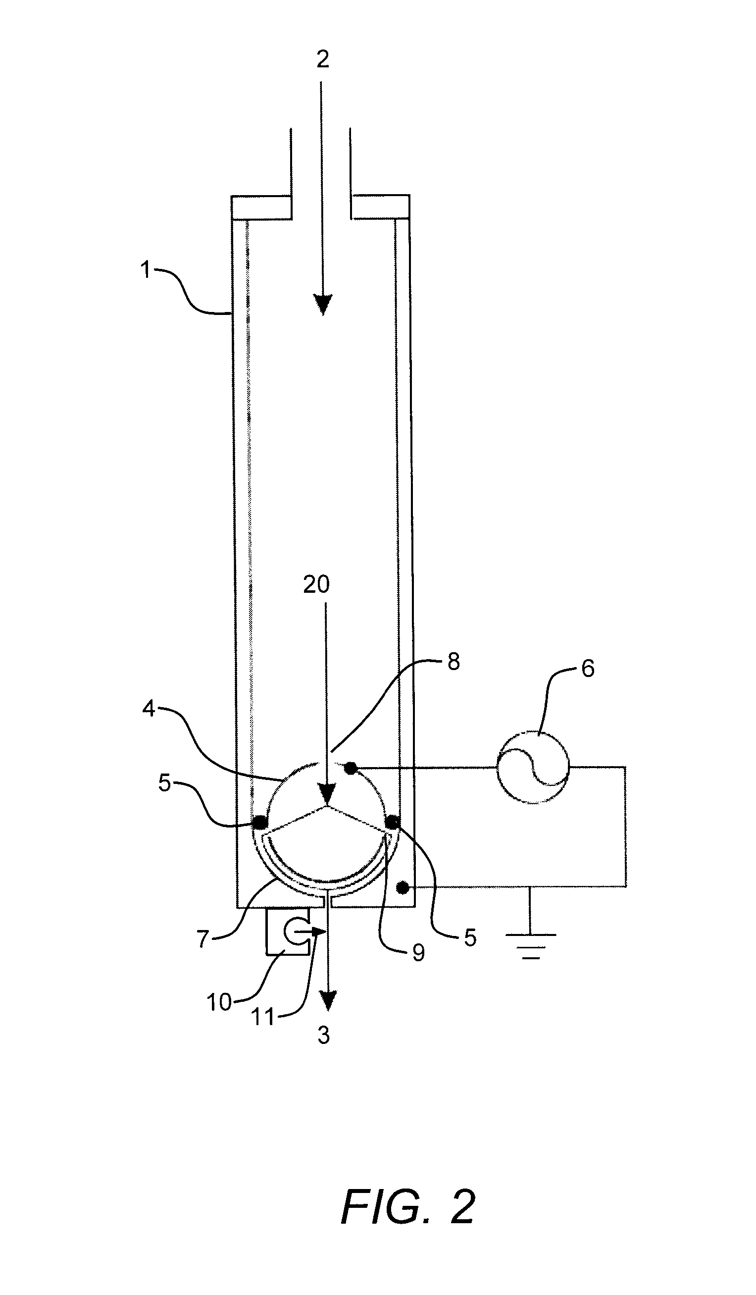
[0067]The apparatus shown in FIG. 2 was used to deposit glass films on silicon wafers. A mixture of helium at 30 L / min and oxygen at 1.5 L / min was fed into the plasma device, while 250 W of RF power at 27.12 MHz was supplied to generate the discharge. Hexamethyldisiloxane was dispersed into helium carrier gas and introduced to the apparatus through the precursor distributor located 1.0 mm away from the outlet of the duct. A silicon wafer, 10.0 cm in diameter, was placed on a holder 5.0 mm downstream of the distributor, and spun at a rate of ˜150 RPM. Listed in TABLE 3 is the dependence of the average thickness of the glass film on the substrate exposure time. The average deposition rate is shown in the third column of the Table, which is calculated by dividing the average film thickness by the time and multiplying this quantity by the area of the wafer (78.5 cm2) divided by the area of the plasma beam (0.4 cm2).

[0068]

TABLE 3Deposition of glass films with the ...


PUM

PropertyMeasurementUnit
Lengthaaaaaaaaaa
Lengthaaaaaaaaaa
Temperatureaaaaaaaaaa

Abstract

Devices and methods for generating a low-temperature, atmospheric pressure plasma are disclosed. A plasma device may include a first electrode having an inlet for a gas, a second electrode having an outlet for the gas and disposed proximate to the first electrode to form a substantially uniform gap therebetween. The gas flows along the substantially uniform gap and from a plurality of different directions to converge and flow through the outlet. High frequency electrical power is applied between the first electrode and the second electrode to generate a plasma within the gas flow emerging at the outlet. Precursor chemicals are added to the plasma flow at the outlet. Various electrode designs may be implemented and various applications involving surface treatment of materials with the low-temperature atmospheric plasma, including surface activation, cleaning, sterilization, etching and deposition of thin films are disclosed.

Description

CROSS-REFERENCE TO RELATED APPLICATION[0001]This application claims the benefit under 35 U.S.C. 119(e) of the following U.S. provisional patent applications, which are both incorporated by reference herein:[0002]U.S. Provisional Patent Application No. 60 / 717,605, filed Sep. 16, 2005, and entitled “LOW-TEMPERATURE, REACTIVE GAS SOURCE AND METHODS OF USE”, by Babayan et al.BACKGROUND OF THE INVENTION[0003]1. Field of the Invention[0004]The invention is related to a method and apparatus for generating a low-temperature, atmospheric pressure plasma, and its use for surface treatment and for coating substrates. In particular, the invention is related to a method and apparatus of generating a low-temperature, atmospheric pressure plasma, wherein the plasma produces a linear beam of reactive gas species that is well suited for processing substrate surfaces at high speeds. The invention is further related to specialized products that are made using the method and apparatus for generating th...

Claims


Application Information

Patent Timeline
IPC IPC(8): C23C16/50C23F1/00H01L21/306C23C16/00
CPCC23F4/00H01J37/00H01J37/32825H05H1/2406H01J2237/162H01J2237/3151H05H2001/2412
Inventor BABAYAN, STEVEHICKS, ROBERT
Owner SURFX TECH
Why Eureka
Try Eureka