Selective catalytic reduction via electrolysis of urea

a catalytic reduction and electrolysis technology, applied in electrostatic separation, liquid-gas reaction process, machines/engines, etc., can solve the problems of reducing the heat transfer efficiency to the vaporization chamber, affecting the efficiency of the vaporization chamber, and requiring a substantial amount of heat and quickly stopping, so as to reduce the emissions of nitrogen oxide (nox) and/or particulate matter

Active Publication Date: 2013-03-05
OHIO UNIV
View PDF42 Cites 23 Cited by
  • Summary
  • Abstract
  • Description
  • Claims
  • Application Information

AI Technical Summary

Benefits of technology

[0015]According to another embodiment of the present invention, there is provided a method for reducing nitrogen oxide (NOx) emissions and / or particulate matter in a combustion exhaust gas during ongoing operation. The method comprises injecting ammonia into the combustion exhaust gas upstream of at least one of a selective catalytic reduction (SCR) device, a selective non-catalytic reduction (SNCR) device, or an electrostatic precipitator device. The ammonia is supplied by applying a voltage difference to an electrolytic cell, which includes a cathode having a first conducting component, an anode having a second conducting component, urea, and an alkaline electrolyte composition in electrical communication with the anode and the cathode, where the alkaline electrolyte composition has a hydroxide concentration of at least 0.01 M or a pH of at least 8. The voltage difference is applied across the cathode and the anode, and the voltage difference is sufficient to effect the electrolytic hydrolysis of urea to produce at least NH3.

Problems solved by technology

Therefore, the hydrolysis of urea requires a substantial amount of heat and quickly stops when the supply of heat is withdrawn.
Minerals and other non-volatile substances can adhere to equipment surfaces, such as spray nozzles and the vaporization chamber walls, and build up over time, which may lead to blockage of the spray nozzle or reduced heat transfer efficiency to the vaporization chamber.
Further, the thermal hydrolysis of urea method is also sensitive to the quality of the urea.
For example, formaldehyde present in urea can negatively affect the performance of an SCR system in a way similar to that of using demineralized water.

Method used


Image

  • Selective catalytic reduction via electrolysis of urea
  • Selective catalytic reduction via electrolysis of urea
  • Selective catalytic reduction via electrolysis of urea

Examples


example 1

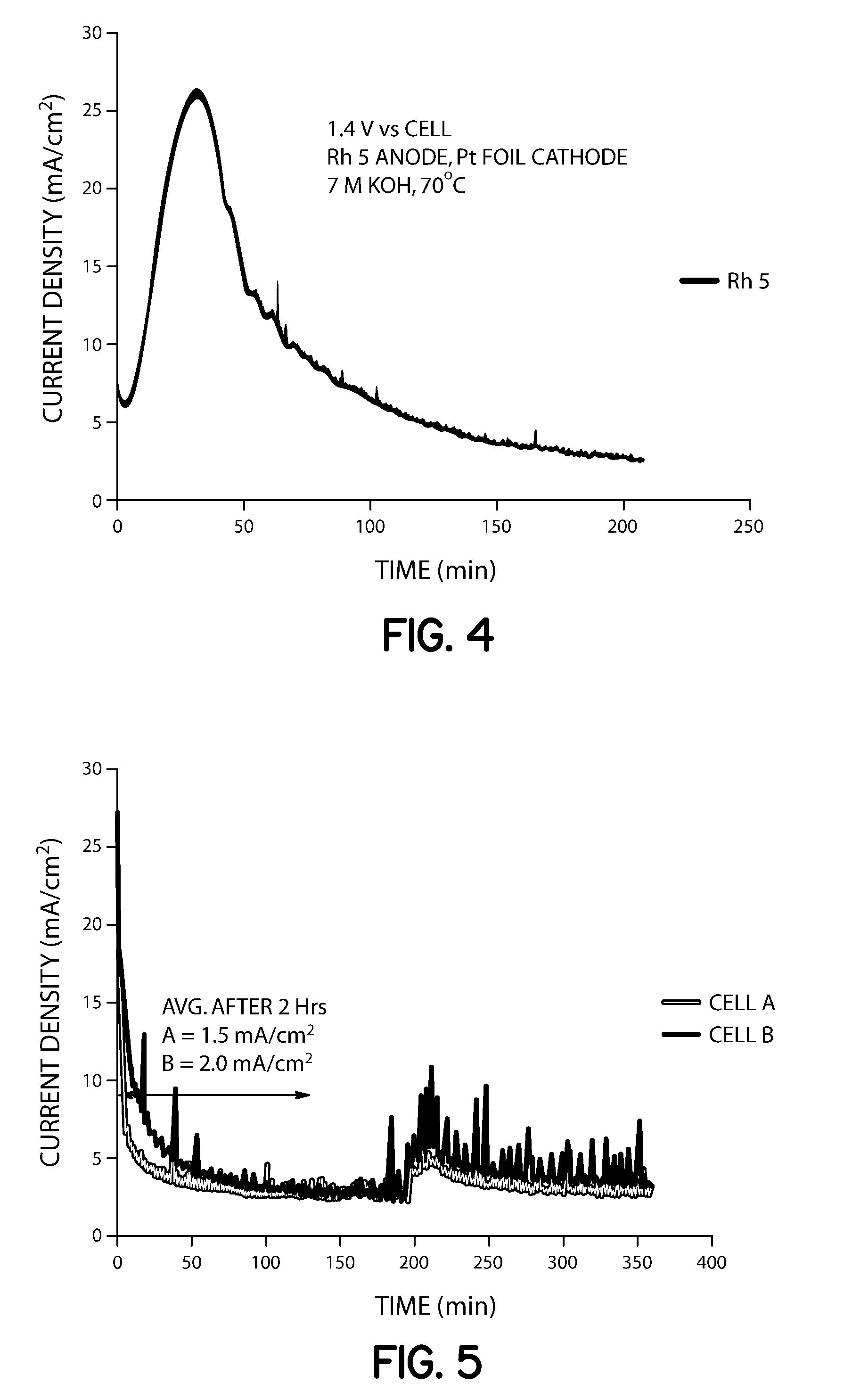
[0055]Two closed cells (1000 mL) were assembled. Each cell was filled with 200 mL of 7 M KOH and 0.33 M urea solution, and stirred at 120 rpm. Voltage (1.4 V) was applied to cell B (supplied with Arbin Industries MSTAT) using a Rh—Ni anode (0.15 mg / cm2 Rh on Ni foil, 10 cm2) and platinum foil (10 cm2) as the cathode. Samples were taken via liquid sampling ports and analyzed for ammonia concentration periodically by extracting 10 mL and diluting 1:100 with distilled water. A 50 mL aliquot of this analyte was added to a flask, 1 mL of pH adjusting solution was added with stirring, and the solution was analyzed using an ion selective electrode. After two hours of constant voltage operation, Cell A and B contained aqueous ammonia concentrations of 3600 and 4700 ppm, respectively (Table 1). After 3 hours of operation, cell A increased to 3800 ppm while cell B increased to 6450 ppm, which provided that the cell with applied potential had 41% higher conversion of urea to ammonia. Cell B av...

example 2

[0058]Two closed cells (1000 mL) were assembled with Rh—Ni anodes (8 cm2 each; cell A: 0.05 mg / cm2, cell B: 0.15 mg / cm2) and platinum foil cathodes (15 cm2), filled with 7 M KOH and 0.33 M urea, and heated to 70° C. Liquid sampling ports were included for monitoring aqueous ammonia concentration ex-situ by ISE throughout the duration of the experiment. Voltage (1.33 V) was applied to both cells A and B (supplied with Arbin Industries MSTAT) with 120 rpm stirring. A lower voltage was chosen as compared to Example 1 above because it was postulated that a lower voltage, which will provide a lower current density, was needed to affect the NiOOH catalyzed reaction to ammonia.

[0059]Samples were taken and analyzed for ammonia concentration periodically by extracting 10 mL and diluting 1:100 with distilled water. A 50 mL aliquot of this analyte was added to a flask with stirrer and ISE electrode and 1 mL of pH adjusting solution, as described in Experiment 1. After two hours of constant vol...

example 3

[0064]Electrolytic Hydrolysis of Urea: A cell containing 7 M KOH / 0.33 M urea solution at atmospheric pressure was subjected to electrolysis-induced hydrolysis. A cell voltage of 1.4 volts was applied to a 2×2.5 cm2 carbon-paper anode deposited with Ni, and a 5×5 cm2 Pt foil cathode. Under these conditions, the presence of ammonia was detected from the conversion of urea into ammonia and carbon dioxide. The hydrolysis pathway becomes favorable with increasing hydroxide salt concentration and increasing temperatures. For example, urea samples contained in 0 M, 1 M, 5 M and 7 M KOH at 50° C. for 89 hours produced 0.7%, 4.2%, 27.4% and 36.7% hydrolysis, respectively. A 7 M KOH sample of urea at 70° C. for 24 hours provided over 95% hydrolysis.


PUM

PropertyMeasurementUnit
voltageaaaaaaaaaa
voltageaaaaaaaaaa
voltageaaaaaaaaaa

Abstract

A method and apparatus for producing ammonia suitable for use as a reductant in a selective catalytic reduction (SCR), a selective non-catalytic reduction (SNCR), or a flue gas conditioning system is provided. A method for treating combustion exhaust gas with ammonia is provided that includes the electrolytic hydrolysis of urea under mild conditions. The electrolysis apparatus includes an electrolytic cell, which may be operatively coupled to an exhaust gas treatment system to provide an apparatus for reducing nitrogen oxides (NOx) and / or particulate in exhaust gases.

Description

CROSS-REFERENCE TO RELATED APPLICATIONS[0001]Pursuant to 37 C.F.R. §1.78(a)(4), this application claims the benefit of and priority to prior filed Provisional Patent Application Ser. No. 61 / 320,447, filed Apr. 2, 2010, which is expressly incorporated herein by reference.FIELD OF INVENTION[0002]The present invention relates to methods and devices for treating exhaust gases.BACKGROUND[0003]There is concern over the environmental impact of emissions from power plants and other fossil fuel combustion sources. For example, the exhaust gas of coal-fired power plants contains chemical pollutants such as nitrogen oxides (“NOx”) and sulfur oxides (“SOx”), as well as particulates, which are also known as “fly ash”. Selective catalytic reduction (SCR) and selective non-catalytic reduction (SNCR) are means for converting nitrogen oxides (NOx) into diatomic nitrogen, N2, and water, H2O. In SCR, a catalyst is used in combination with a gaseous reductant, which is added to a stream of flue or exha...

Claims


Application Information

Patent Timeline
Patent Type & Authority Patents(United States)
IPC IPC(8): B01D53/56C01B3/22B01D53/94B01D53/74C25B1/00F01N3/10C01C1/00C25B1/02
CPCC25B1/00F01N3/2066Y02T10/24F01N2610/02Y02T10/12C25B1/27
Inventor BOTTE, GERARDINE G.
Owner OHIO UNIV
Why Eureka
Try Eureka