Integrated energy and/or synthesis gas production method by in-situ oxygen production, chemical looping combustion and gasification

a gasification and oxygen production technology, applied in the direction of gasification process details, fuel cells, combustible gas production, etc., can solve the problems of high investment cost, high energy consumption, and significant increase of the overall capture cos

Inactive Publication Date: 2013-04-16
INST FR DU PETROLE
View PDF9 Cites 26 Cited by
  • Summary
  • Abstract
  • Description
  • Claims
  • Application Information

AI Technical Summary

Benefits of technology

[0083]The advantages of the invention listed below are described by way of non imitative example.
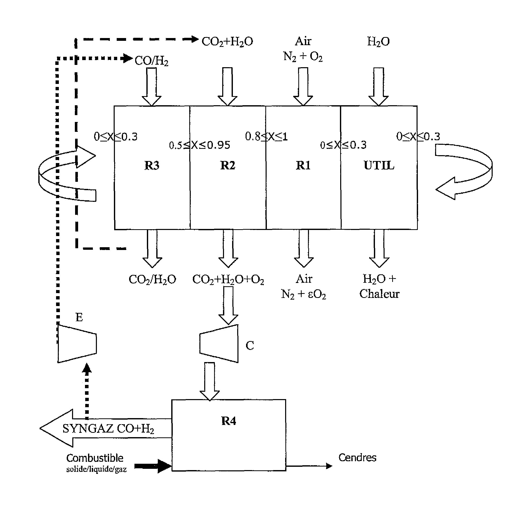
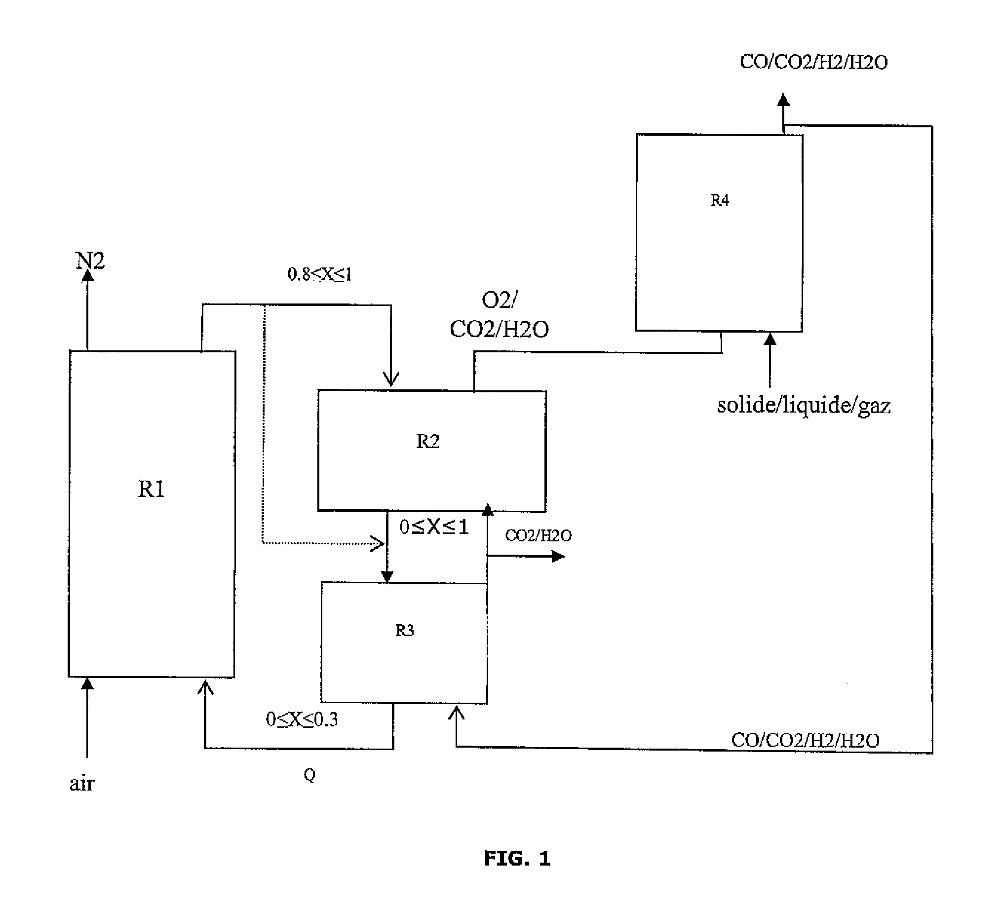
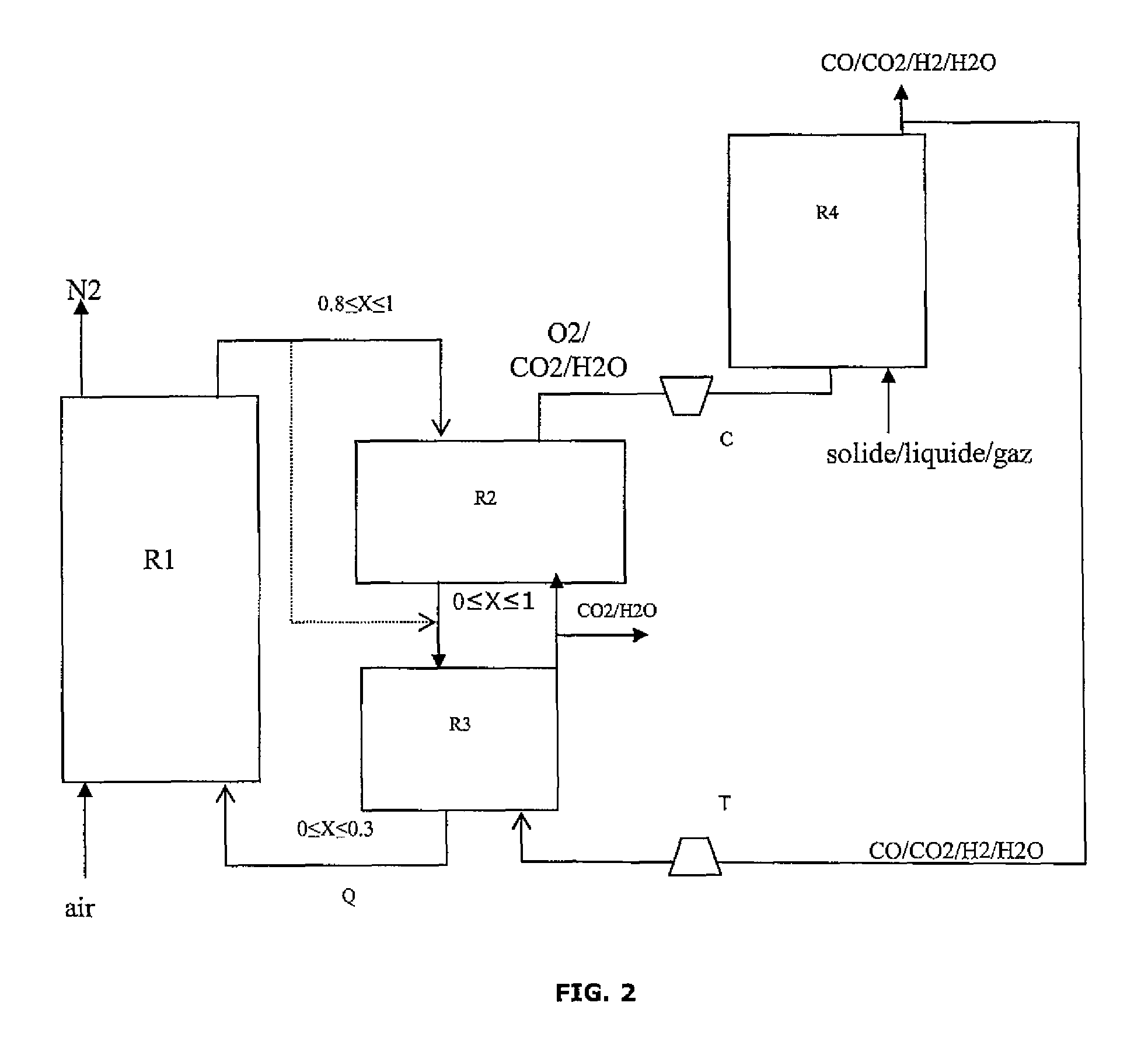
[0084]1. The invention allows coupling between the chemical looping combustion process, the gasification process and oxygen production.

Problems solved by technology

One drawback of this combustion mode and of ASUs in particular is their high energy consumption and their high investment cost that significantly increases the overall capture cost.
They are carried along with the oxygen carrier into the air reactor where they are burned, which however produces CO2 mixed nitrogen, which affects the capture rate of the unit.
To avoid this, it is necessary to have a specific equipment for separation between particles of different nature but of comparable size, hence the complexity of the system, in particular in the case of large-scale industrial extrapolation.
This method requires high steam flow rates, and it is therefore necessary to heat and to evaporate a large amount of water prior to feeding it into the oxidation reactor, which leads to a limiting energy balance.
However, a problem that faces the person skilled in the art wanting to produce synthesis gas (therefore hydrogen) by gasification is the kinetics of the reactions that take place in the gasification reactor, as well as the high reaction temperatures in the gasification reactor.
The residence time required for the reactants is thus long.
This directly affects the size of the plants and, more specifically, the size of the reactors involved, which leads to high investment costs.

Method used


Image

  • Integrated energy and/or synthesis gas production method by in-situ oxygen production, chemical looping combustion and gasification
  • Integrated energy and/or synthesis gas production method by in-situ oxygen production, chemical looping combustion and gasification
  • Integrated energy and/or synthesis gas production method by in-situ oxygen production, chemical looping combustion and gasification

Examples


example 1

Operation of the Integrated Method According to the Invention

[0095]The operating conditions considered in each stage are as follows:

[0096]Gasification

[0097]1) the gasification reaction is carried out autothermally at a temperature that depends on the exothermicity of the reaction, therefore on the amount of oxygen introduced;

[0098]2) the fluidization parameters are not taken into account;

[0099]3) the reactants are the solid or liquid feed;

[0100]4) the reaction is endothermic in the absence of oxygen.

[0101]Reduction

[0102]1) the reduction reaction is complete. The reaction products are CO2 and H2O;

[0103]2) the exchange is ideal between the oxygen carrier and the gaseous fuel: there is no diffusion limitation, no carbon formation, no reactivity loss;

[0104]3) the reaction is exothermic.

[0105]Oxidation

[0106]1) the oxidation reaction is complete;

[0107]2) the exchange is ideal between the oxygen carrier and the air;

[0108]3) the reaction is exothermic.

[0109]Oxygen Production

[0110]1) the pro...

example 2

Synthesis Gas Production

[0127]The present invention allows to adjust the production between maximization of the thermal energy produced by the method and maximization of the amount of synthesis gas (syngas) at the process output in relation to the amount of hydrocarbon feed introduced.

[0128]In the present example, one wants to maximize the amount of synthesis gas produced.

[0129]Oxygen Production Reactor:

[0130]The oxygen carrier solid is swept with a gas to maintain the oxygen partial pressure low. This gas also serves as a carrier gas for transporting the oxygen to the gasifier. The hot gases resulting from the combustion of the synthesis gas on the solid, three quarters of which are recycled, are used here. This gas consists of water and carbon dioxide, it flows in at a temperature of 902° C. and at a flow rate of 11.4 kmol / h. The oxygen production reaction is endothermic and it consumes 444 kW in form of heat.

[0131]Solid Phase:

[0132]

reactor inlet,reactor outlet,OxideT° = 900° C.T°...

example 3

Heat Production

[0161]The present invention allows to adjust the production between:

[0162]maximization of the thermal energy produced by the process,

[0163]or maximization of the amount of synthesis gas (syngas) leaving the process in relation to the amount of hydrocarbon feed introduced.

[0164]In the present example, one wants to maximize the amount of heat produced by the process.

[0165]Oxygen Production Reactor:

[0166]The oxygen carrier solid is swept with a gas to maintain the oxygen partial pressure low. This gas also serves as a carrier gas for transporting the oxygen to the gasifier. The hot gases resulting from the combustion of the synthesis gas on the solid, three quarters of which are recycled, are used here. This gas consists of water and carbon dioxide, it flows in at a temperature of 934° C. and at a flow rate of 169 kmol / h. The oxygen production reaction is endothermic and it consumes 444 kW in form of heat.

[0167]Solid phase:

[0168]

Reactor inlet,Reactor outlet,OxideT° = 900...


PUM

PropertyMeasurementUnit
boiling point temperatureaaaaaaaaaa
pressuresaaaaaaaaaa
temperatureaaaaaaaaaa

Abstract

The invention relates to an integrated method of in-situ oxygen production, chemical looping combustion and gasification of liquid, solid or gaseous fuels allowing combustion of coal, petroleum coke and / or liquid hydrocarbons and notably heavy and / or extra heavy or bituminous residues for production of synthesis gas under pressure and / or energy.

Description

FIELD OF THE INVENTIONContext: Chemical Looping CO2 Capture[0001]Considering the climate changes observed during the past decades and those predictable in the long term, controlling greenhouse gas emissions is becoming an increasingly strong requirement for all economic sectors, in particular those concerning energy production. One of the various possible ways of controlling greenhouse gas discharge to the atmosphere is carbon capture and sequestration. This option is specially suited in case of a centralized use of fossil energies. The most part of the solutions considered induce a high energy penalty, with an autoconsumption of the order of 20% to 30%.BACKGROUND OF THE INVENTION[0002]Among the combustion means allowing CO2 capture, oxycombustion units afford the advantage of producing combustion fumes free of nitrogen from the combustion air since combustion is achieved from pure oxygen. Such a method is for example described in patent WO-2007 / 039,687 A. This oxygen is produced by...

Claims


Application Information

Patent Timeline
Patent Type & Authority Patents(United States)
IPC IPC(8): B01J7/00C01B6/24C10J3/16C10J3/00C01B3/36
CPCC01B3/36C01B3/46C01B13/0203C10J3/725C01B2203/0255C10J2300/0959C10J2300/1807Y02P20/10
Inventor HOTEIT, ALIGUILLOU, FLORENTLAMBERT, ARNOLDROESLER, JOHN
Owner INST FR DU PETROLE
Why Eureka
Try Eureka