

Electrode head of the plasma cutting machine
a plasma cutting machine and electrode head technology, applied in plasma welding apparatus, gas-filled discharge tubes, manufacturing tools, etc., can solve the problems of not easy to process, assemble or disassemble the electrode head, not easy to fix the workpieces on the jig, and the installation of the jig or the fixation of the workpiece on the jig, so as to achieve less defective or deformed electrode heads, high compression force, and high engagement strength
- Summary
- Abstract
- Description
- Claims
- Application Information
AI Technical Summary
Benefits of technology
Problems solved by technology
Method used
Image

Examples
Embodiment Construction
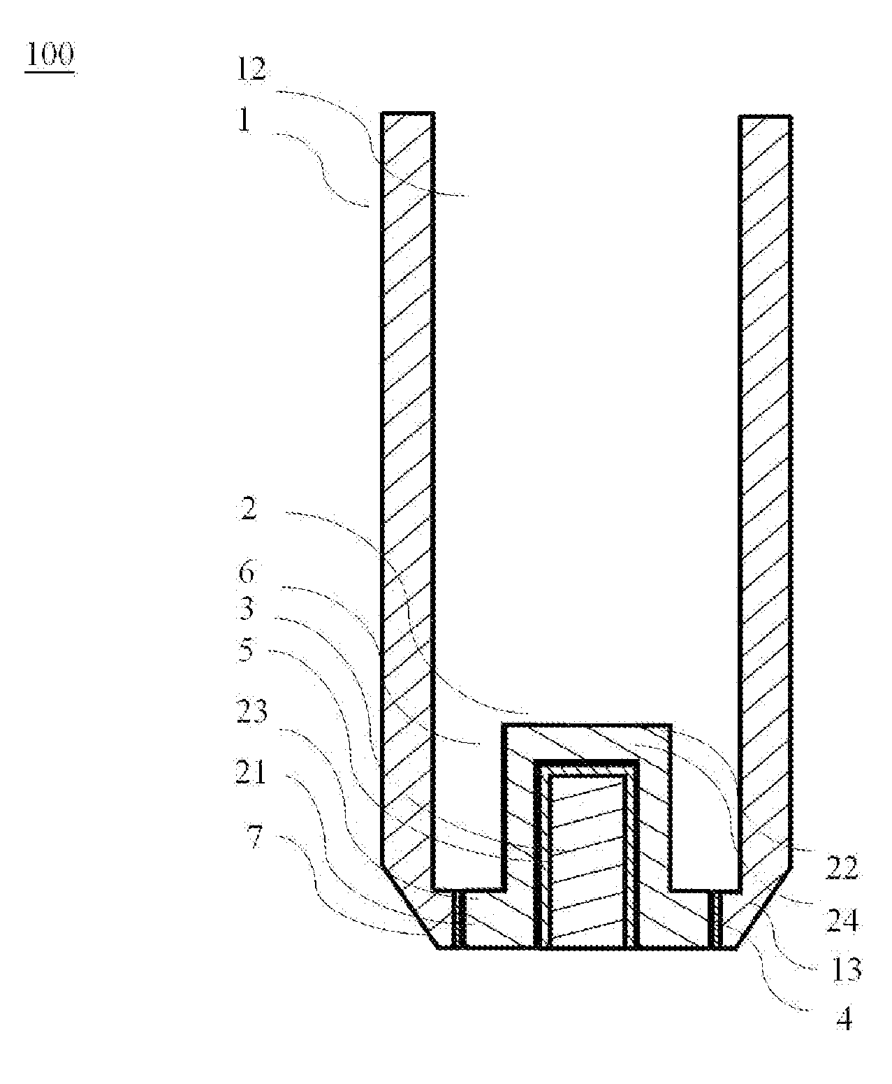
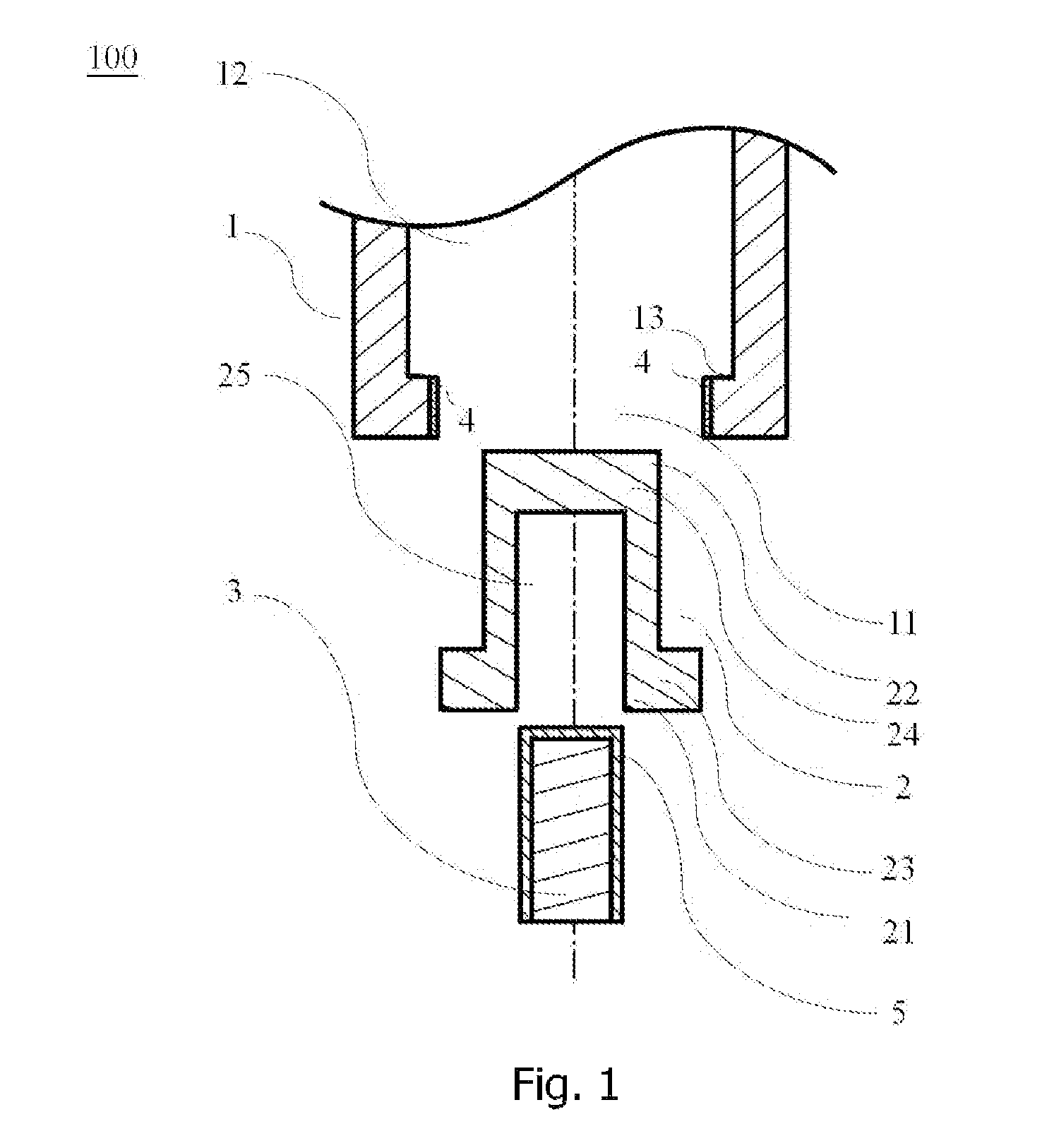
[0018]Some particular embodiments of the invention will be described in detail for purpose of illustration, and one of ordinary skill in the art can easily understand the advantages and efficacy of the present invention through the disclosure of the specification. It is to be understood that alternative embodiments may be possible for the implement and application of the present invention while numerous variations will be possible to the details disclosed in the specification on the strength of diverse concepts and applications without going outside the scope of the invention as disclosed in the claims.
[0019]The present invention disclose an electrode head of the plasma cutting machine, wherein the concept and the working method of the plasma cutting machine is well known by those having ordinary skills in the art, therefore the description below will not describe it in detail.
[0020]It's necessary for the electrode head of the plasma cutting machine to have high electrical conductiv...
PUM
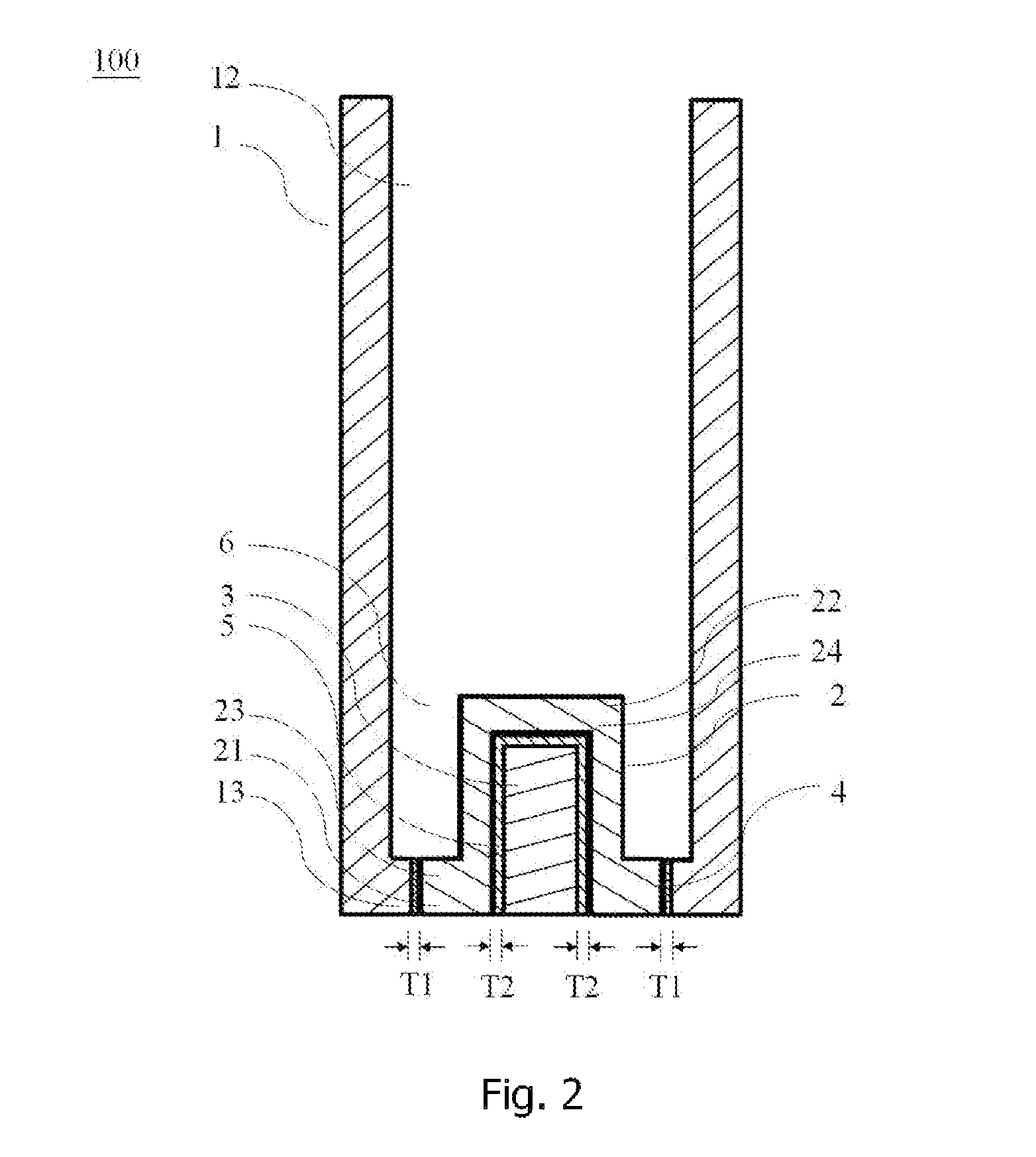
| Property | Measurement | Unit |
|---|---|---|
| thickness | aaaaa | aaaaa |
| thickness T2 | aaaaa | aaaaa |
| thickness T1 | aaaaa | aaaaa |
Abstract
Description
Claims
Application Information