Microfluidic device having a flow channel

a microfluidic device and flow channel technology, which is applied in the field of microfluidic devices having flow channels, can solve the problems of gas bubbles in microfluidic devices, adversely affecting the accuracy of the flow rate, and the presence of gas bubbles also adversely affecting the mixing of liquids, so as to improve the accuracy and consistency of analytical results, improve the accuracy of priming activity, and facilitate assembly

Inactive Publication Date: 2013-06-11
ABBOTT LAB INC
View PDF38 Cites 3 Cited by
  • Summary
  • Abstract
  • Description
  • Claims
  • Application Information

AI Technical Summary

Benefits of technology

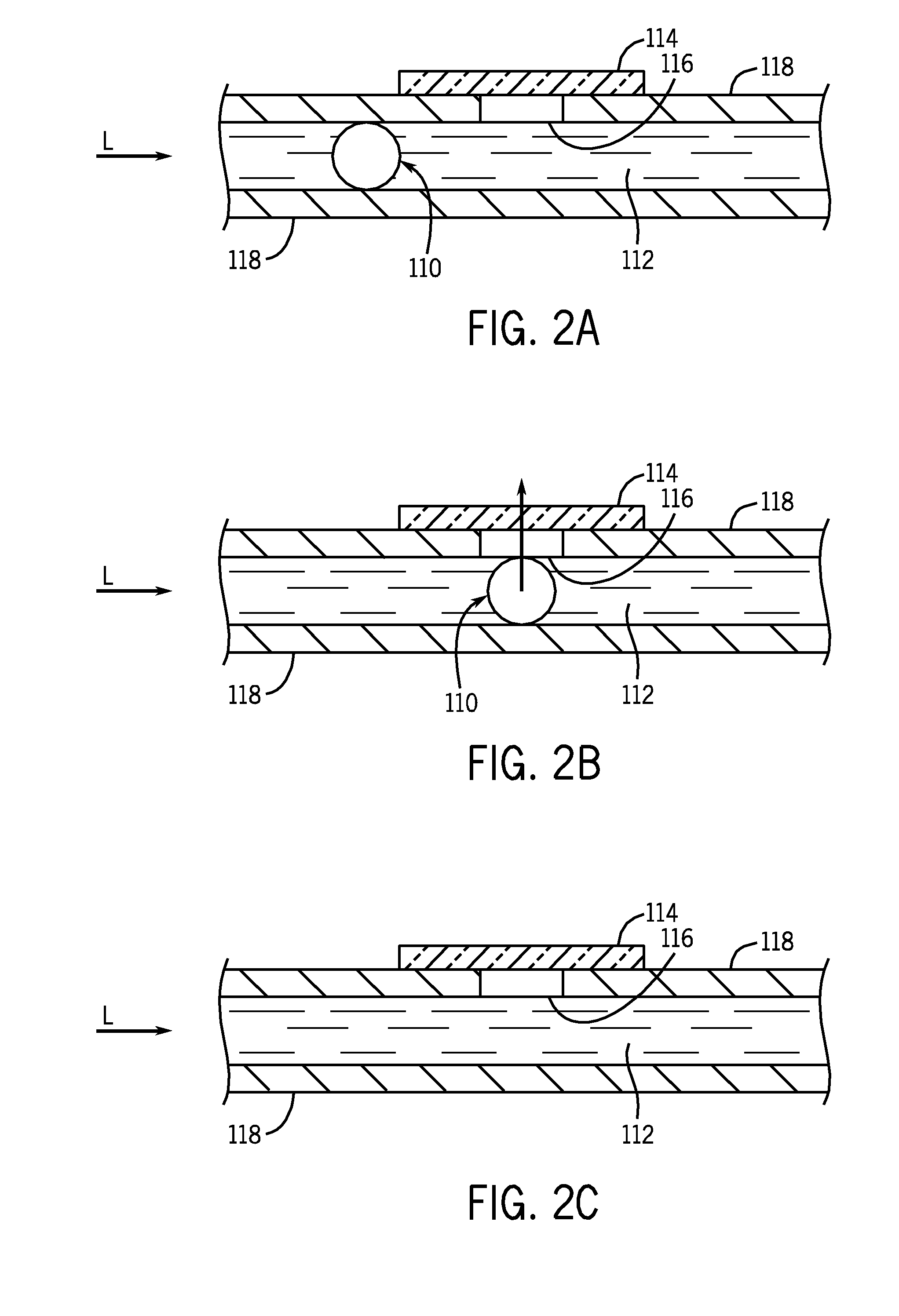
[0016]This invention provides a microfluidic device having a flow channel comprising a hydrophobic membrane to improve control of flow and control of processing conditions in the flow channel, and to improve the removal of gas bubbles from the flow channel of the microfluidic device. In addition, the invention enables the process controls of the microfluidic device to know when gas bubbles have been removed, so that the next step in the process can be carried out.
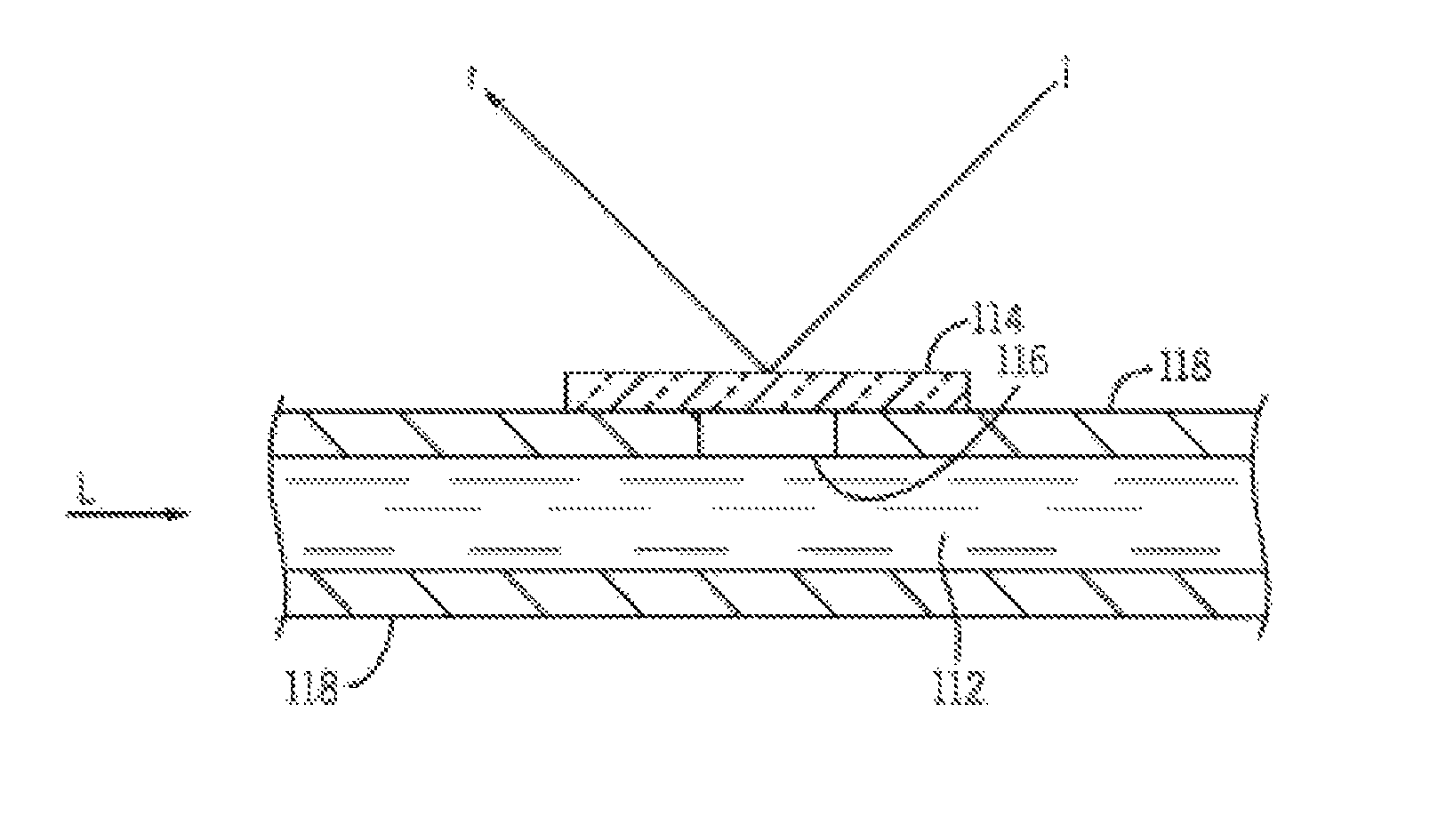
[0018]Control loops, which can be open loops or closed loops, are provided to synchronize and program reactions in the assay and other analytical activities in the microfluidic device. Sensors for monitoring and controlling assay steps and other analytical activities can be located at points in the flow channel where reagents are introduced, at points in the flow channel where reactants are mixed, at points in the flow channel where reactions take place, and at points in the flow channel where the results of reactions are read. A feedback loop can be provided to monitor the step of removing gas bubbles. It is preferred that monitoring be carried out by optical methods, such as, for example, reflection of light from the surface of the hydrophobic membrane. The information allows the microfluidic device to determine the beginning and the end of the step of removing gas bubbles from the flow channel.
[0019]The benefits and advantages of the microfluidic device described herein include, but are not limited to: (a) more accurate and consistent analytical results by removing the variations caused by gas bubbles; (b) accurate status of priming activities, if the flow channels need to be primed before reagents are introduced into the flow channels; (c) built-in quality checks of the flow channels by monitoring abnormal flow behavior of samples and reagents by means of optical monitoring; (d) ease of assembly of microfluidic devices by using thermoplastic materials for all required components of the device; (e) avoidance of degassing for those reagents that have a tendency to expel gas over a period of time; and (f) enable detection of reactions that generate gaseous byproducts.

Problems solved by technology

Gas bubbles in microfluidic devices occur when the flow channels of the devices are not fully primed.
The presence of gas bubbles adversely affects the precision of the rate of flow.
The presence of gas bubbles also adversely affects the mixing of liquids.
Gas bubbles often interfere with optical measurements, if optical detection is required.
Optical signals cannot differentiate a gas from a liquid.
The presence of gas bubbles in flow channels makes it difficult to determine accurate quantities of reagents for chemical reactions.
If chemical reactions are called for, reaction kinetics cannot be controlled on account of the uncertainty of the volume of gas and interference caused by the presence of gas bubbles.
For liquids having a high surface tension, such as, for example, water, gas bubbles present an obstacle to flow in a flow channel.
However, the device and system described herein cannot control the timing of an actual chemical reaction subsequent to the mixing step.
However, the device requires external pumps and valves.
The patent does not disclose microchannels and removal of localized gas bubbles, nor does the patent disclose detection of gas bubbles to control reaction kinetics.
However, the device requires external pumps and valves.
The patent also does not disclose reaction kinetics.
This device does not make use of a hydrophobic membrane to aid in the removal of gas bubbles.
Microfluidic devices dramatically reduce the quantities of reagents and samples, thereby resulting in lowered costs.
Detection of gas bubbles is required because access to and control of the chemical reaction or kinetics as reactants pass through the system is difficult.

Method used


Image

  • Microfluidic device having a flow channel
  • Microfluidic device having a flow channel
  • Microfluidic device having a flow channel

Examples


example 1

[0062]Measurement of the concentration of cocaine enables confirmation of substance abuse. The assay for cocaine is based on the competition between a drug labeled with an enzyme and the drug from a sample of urine for a fixed number of binding sites on an antibody that specifically binds to the drug. In the absence of the drug from the sample of urine, the antibody binds to the drug labeled with the enzyme glucose-6-phosphate dehydrogenase (G6PDH), and the enzyme activity is inhibited. The G6PDH enzyme activity is determined spectrophotometrically at 340 / 412 nm by measuring the ability of the enzyme to convert nicotinamide adenine dinucleotide (NAD) to NADH, the reduced form of NAD.

[0063]The reactive ingredients involve two reagents, Reagent 1 and Reagent 2. Reagent 1 comprises anti-benzoylecgonine monoclonal antibodies (mouse), glucose-6-phosphate (G6P), and nicotinamide adenine dinucleotide (NAD). Reagent 2 comprises benzoylecgonine labeled with glucose-6-phosphate dehydrogenase ...

example 2

[0067]Measurement of the concentration of creatinine enables assessment of renal function. At an alkaline pH, creatinine in the sample (serum, plasma, urine) reacts with picrate to form a creatinine picrate complex. The rate of increase in absorbance at 500 nm due to the formation of this complex is directly proportional to the concentration of creatinine in the sample.

[0068]The reactive ingredients involve two reagents, Reagent 1 and Reagent 2. Reagent 1 comprises sodium hydroxide. Reagent 2 comprises picric acid.

[0069]Measurement is carried out by means of a spectrophotometer at 500 nm. Results are determined at the stable reading after reaction.

[0070]Additional information is set forth on the package insert marked ARCH ITECT / AEROSET Creatinine, Ref 7D64-20, incorporated herein by reference. See, for example, AEROSET System Operations manual 200154-101-November 2004, pages 3-7 and 3-9 through 3-11, inclusive, incorporated herein by reference.

[0071]According to the package insert, ...

example 3

[0072]Measurement of the concentration of ethanol enables the determination of a person's level of intoxication for legal or medical reasons. In the presence of alcohol dehydrogenase and nicotinamide adenine dinucleotide (NAD), ethanol is readily oxidized to acetaldehyde and NADH. The enzymatic reaction can be monitored spectrophotometrically at 340 / 412 nm.

[0073]The reactive ingredients involve two reagents, Reagent 1 and Reagent 2. Reagent 1 comprises Tris buffer. Reagent 2 comprises alcohol dehydrogenase (ADH) and NAD.

[0074]Measurement is carried out by means of a spectrophotometer at 340 / 412 nm (the reading of absorbance taken at the secondary wavelength is subtracted from the reading of absorbance taken at the primary wavelength, and the difference is used as the absorbance value). Results are determined at the stable reading after reaction.

[0075]Additional information is set forth on the package insert marked ARCHITECT / AEROSET MULTIGENT ETHANOL; Ref 3L36-20, incorporated herein...


PUM

PropertyMeasurementUnit
thicknessaaaaaaaaaa
pore sizeaaaaaaaaaa
heightaaaaaaaaaa

Abstract

A microfluidic device having a flow channel comprising a hydrophobic membrane to improve control of flow and control of processing conditions in the flow channel, and to improve the removal of gas bubbles from the flow channel of the microfluidic device. In addition, the invention enables the process controls of the microfluidic device to know when gas bubbles have been removed, so that the next step in the process can be carried out.

Description

BACKGROUND OF THE INVENTION[0001]1. Field of the Invention[0002]This invention relates to a system for removing gas bubbles from a flow channel in a microfluidic device.[0003]2. Discussion of the Art[0004]Microfluidic devices are designed to carry out analytical processes in a limited space, i.e., small reaction chambers and flow channels. In a sealed microfluidic device, the formation of gas bubbles in the flow channels is inevitable on account of such operational steps as mixing, dilution, separation, and other steps. In general, gas bubbles are removed from solutions by incorporating vent holes in a conduit to allow gas to escape. Gas bubbles in microfluidic devices occur when the flow channels of the devices are not fully primed. Gas bubbles are formed when plugs of liquid collide during a mixing step. Gas bubbles are formed by electrolysis of water around electrodes when the flow of liquid is driven by electrokinetic forces. The presence of gas bubbles adversely affects the pre...

Claims


Application Information

Patent Timeline
Patent Type & Authority Patents(United States)
IPC IPC(8): G01N33/00G01N33/48B01L3/00
CPCB01L3/502723B01L3/502784B01L2200/0673B01L2200/0684B01L2200/143B01L2300/0645B01L2300/0654B01L2300/0681B01L2300/0816B01L2300/161
Inventor YANG, TAHUA
Owner ABBOTT LAB INC
Why Eureka
Try Eureka