
Microfluidic device for cell culture

a cell culture and microfluidic technology, applied in the field of microfluidic cell culture apparatuses, can solve the problems of limited improvement of cell cultured cell function, difficulty in mimicking complex in vivo microenvironment that modulates cellular function, and inability to achieve long-term cell culture success, etc., to promote cell polarity, promote efficient and effective transport, and encourage cell polarity

Active Publication Date: 2013-07-09
CORNING INC
View PDF42 Cites 28 Cited by
  • Summary
  • Abstract
  • Description
  • Claims
  • Application Information

AI Technical Summary

Benefits of technology

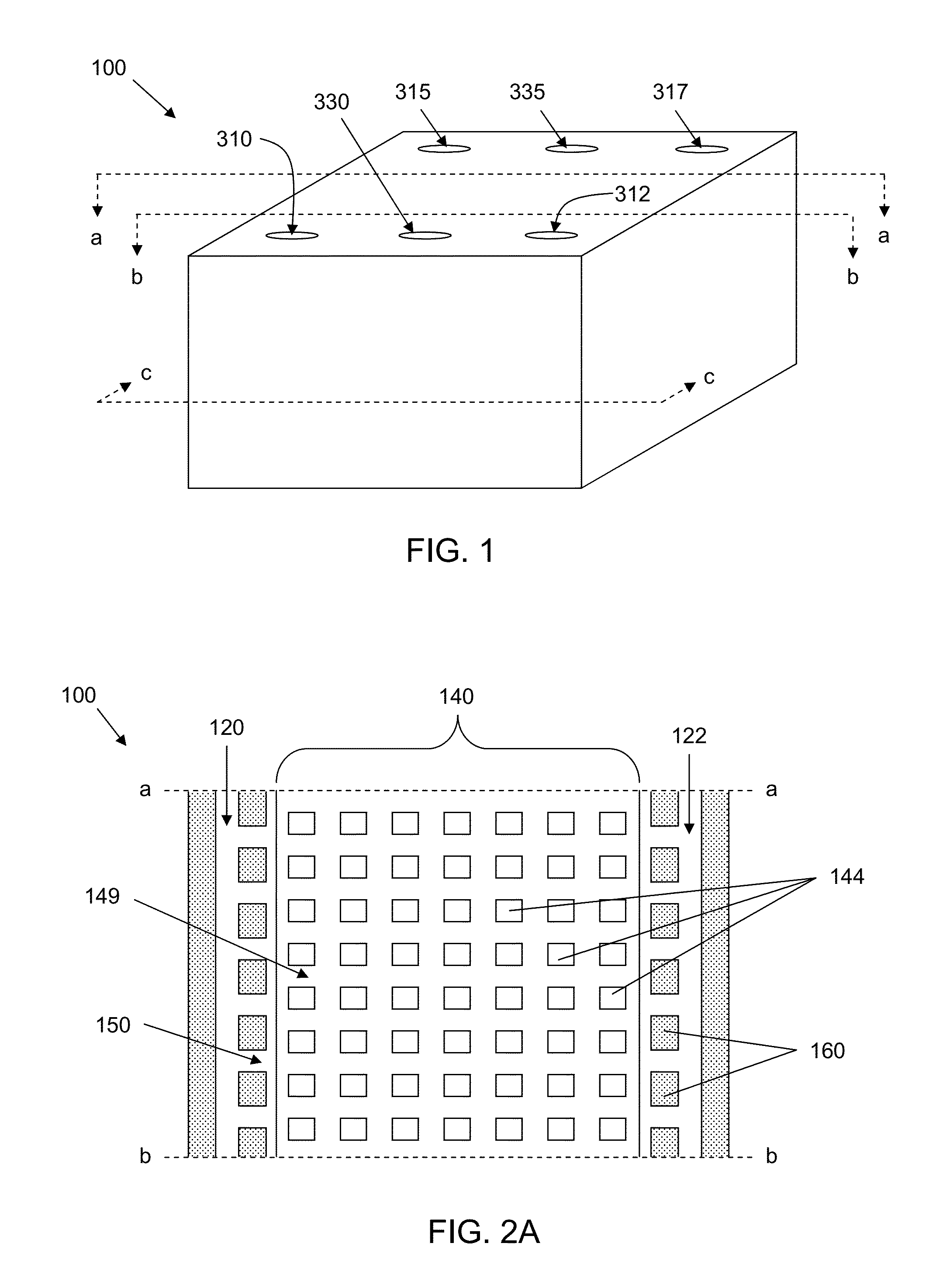
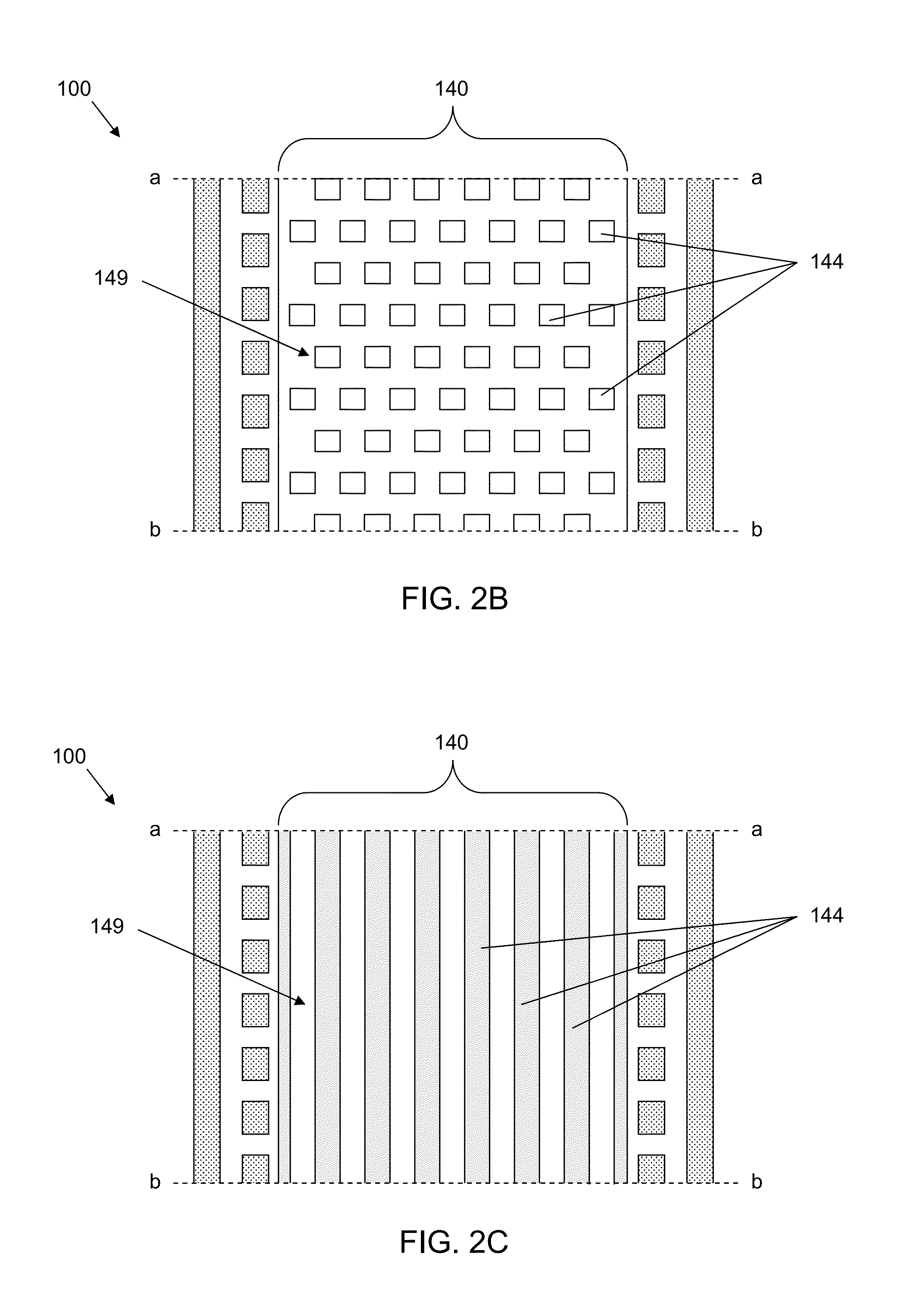
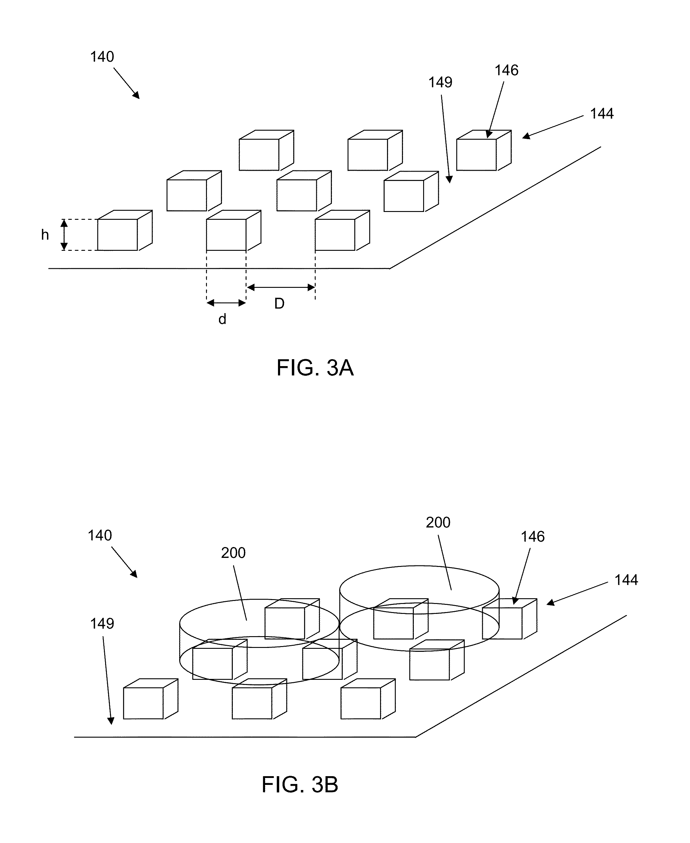
[0007]The structured surfaces may form one or more troughs through which fluid may flow. The bottom of the troughs may be formed by the bottom of the structured surface and the sides of the projections may form the sides of the trough. In various embodiments, the microfluidic culture devices have an inlet and outlet in fluid communication with one or more troughs of the structured surfaces that allow fluid to be introduced into or removed from the troughs. In situations where the cultured cells form tight cell-cell junctions (e.g., adopt tissue like morphology), the cells may fluidly isolate the troughs and the perfusion channel, allowing independent gradients to be formed across the cell chamber. In addition, the trough(s) and perfusion channel can be effectively used to simulate multidirectional flow in vivo. In some cases, the carious gradients that may result or the multidirectional flow may encourage cell polarity.
[0008]The devices and methods described herein may provide one or more advantages over prior microfluidic or other culture devices. For example, embodiments of the devices described herein may provide structural design to enable 3D tissue-like organization of cells and restoration of in vivo-like membrane polarity, may provide sustainable dynamic in vivo-like conditions for long-term cell culture and cell-specific functionality in vitro for evaluation of toxicity (including chronic toxicity) and studies of drug-drug interaction (over longer term), may provide dynamic cell culture conditions, such as controlled supply of oxygen and nutrients, oxygen gradient and shear stress control, and may allow for control of oxygen levels and nutrients to mimic physiological conditions. The multiple flow channels provide efficient and effective transport of nutrients, removal of waste, and supply of oxygen. The troughs and perfusion channel can be effectively used independently to generate gradients across the cell chamber and simulate multidirectional flow in vivo. A perfusion regime that promotes the restoration of polarity and extends a bile canalicular structure in three dimensions can be realized. These and other advantages of the various embodiments of the devices and methods described herein will be readily apparent to those of skill in the art upon reading the disclosure presented herein.

Problems solved by technology

However, if results from such testing are not indicative of responses from cells in vivo, the relevance of the results may be diminished.
However, mimicking complex in vivo microenvironment that modulates cellular function for successful long-term cultures of cells remains a challenge.
Accordingly, even with such advances, limited improvement in cell cultured cell function has been achieved.

Method used


Image

  • Microfluidic device for cell culture
  • Microfluidic device for cell culture
  • Microfluidic device for cell culture

Examples


example 1

Device Fabrication and Assembly

[0094]Four inch silicone wafers were primed with P-20 (Microprime Primer P-20, Shin-Etsu MicroSi, Phoenix, Ariz.), and a 1 um thick Shipley 1813 photoresist (Rohm and Haas, Philadelphia, Pa.) was spun on the wafer at 3000 rpm for 30 sec (acceleration 1000 rpm / s) and soft baked on a hot plate for 1 min at 110° C. The wafers were exposed to UV-light through a chromium mask with the desired structures designed as CAD-drawing using MA6 (Karl Suss) mask aligner. After post bake of 2 min at 80° C. the wafers were finally developed (60-100 s, MF-319, Shipley), thoroughly rinsed with water and dried. Molds for 15 um deep troughs and 45 um deep fluidic channels and cell culture chamber were etched into the silicone using Plasma Therm 72 fluorine based reactive ion etcher. After photoresist stripping and cleaning silicone masters were exposed to trichloro(1H, 1H, 2H, 2H)-perfluorooctyl vapor for 2 h for passivation. Polydimethylsiloxane (PDMS) replicas were prod...

example 2

Fluidic Characterization of the Microfluidic Device

[0098]To test the mass transfer inside the device between perfusion channels and cell incubation chamber subsequent injections solutions of Sulforhodamine B (8.9×10⁻⁵ M SRB in PBS buffer) and carboxyfluoresceine (4×10⁻⁵ M in PBS buffer) dyes was performed employing a microfluidic device having a single inlet and outlet for both the left and right perfusion channels. An increase of Sulforhodamine B fluorescence intensity in the cell culture chamber was observed as a function of flow rate and time (FIG. 23A) indicating good fluidic transport across the retention barrier (posts) and between the perfusion channels and the cell chamber. Conversely, when the fluorescein (4×10⁻⁵ M in PBS buffer) was introduced via the cell chamber inlet, an increase in fluorescent intensity across the retention barrier (posts) and filling the perfusion channels was observed (FIG. 23B). In the images shown in FIGS. 23A and 23B, the left side of the image is...

example 3

Long Term Cell Culture in Microfluidic Devices

[0101]Incubation of human primary hepatocytes in the microfluidic devices was performed to demonstrate the ability of supporting phenotypically active cell population for prolonged periods of time. 5,000-10,000 primary human hepatocyte cells (Cryopreserved human hepatocytes, XenoTech, Lenexa, Kans.) were plated to the microfluidic devices (via cell chamber port) and the devices were perfused with MFE cell culture medium in open-loop mode at 1 ul / min flow rate. Cell culture media was manually changed daily in 96 well plates cultures. Devices were monitored daily to track possible changes in cell morphology and health. At different time points the incubation was stopped and a live / dead stain (LIVE / DEAD viability / cytotoxicity kit for mammalian cells from Molecular Probes, Eugene, Oreg.) was performed to monitor cell survival rate and morphology. Images of cells packed in the device and the results of live / dead stain are shown in FIGS. 25-26...


PUM

PropertyMeasurementUnit
heightaaaaaaaaaa
distanceaaaaaaaaaa
distanceaaaaaaaaaa

Abstract

A microfluidic cell culture apparatus includes a cell retention chamber and a perfusion channel. The cell retention chamber has a structured surface. The structured surface includes a major surface from which a plurality of projections extends into the chamber. The plurality of projections are arranged to suspend cells cultured in the chamber above the major surface. The first perfusion channel is configured to provide laminar flow of a fluid through the channel and forms a plurality of openings in communication with the cell retention chamber. The openings are configured to prevent cells from the retention chamber from entering the perfusion channel.

Description

CLAIMING BENEFIT OF PRIOR FILED U.S. APPLICATION[0001]This application claims the benefit of U.S. Provisional Application Ser. No. 61 / 250,754, filed on Oct. 12, 2009. The content of this document and the entire disclosure of publications, patents, and patent documents mentioned herein are incorporated by reference.FIELD[0002]The present disclosure relates to apparatus for culturing cells; more particularly to microfluidic cell culture apparatuses.BACKGROUND[0003]Cells cultured on flat cell culture ware often provide artificial two-dimensional sheets of cells that may have significantly different morphology and function from their in vivo counterparts. Cultured cells are important to modern drug discovery and development and are widely used for drug testing. However, if results from such testing are not indicative of responses from cells in vivo, the relevance of the results may be diminished. Cells in the human body experience three dimensional environments completely surrounded by ...

Claims


Application Information

Patent Timeline
Patent Type & Authority Patents(United States)
IPC IPC(8): C12M3/00
CPCC12M21/08C12M23/16C12M23/24C12M23/40C12M29/10G01N33/5008
Inventor FARIS, RONALD A.GORAL, VASILIY N.HSIEH, MIYA YI-CHENGPETZOLD, ODESSA N.YUEN, PO KI
Owner CORNING INC
Learn More