Fouling resistant membranes formed with polyacrylonitrile graft copolymers

a polyacrylonitrile and amphiphilic graft technology, applied in water/sewage treatment, osmosis/dialysis, separation processes, etc., can solve the problems of reducing the lifetime of the membrane, affecting the filtration effect, and increasing the energy requirements

Active Publication Date: 2013-08-13
THE UNITED STATES OF AMERICA AS REPRESENTED BY THE SECRETARY OF THE NAVY +1
View PDF43 Cites 26 Cited by
  • Summary
  • Abstract
  • Description
  • Claims
  • Application Information

AI Technical Summary

Problems solved by technology

Membrane fouling is one of the more important problems in the membrane industry.
Flux decline typically leads to higher energy requirements, and frequent cleaning is usually required to remedy this.
This is only a temporary solution, and fouling typically ultimately reduces the lifetime of the membrane.
This method, however, only functionalizes the top surface of the membrane, so the fouling of internal pores is not prevented.
A significant drawback of these surface modification methods is the use of high-energy gamma radiation or plasmas to initiate graft polymerization.
These approaches may significantly increase membrane fabrication cost and are poorly controlled.
Undesirable side reactions include polymerization of ungrafted chains, which are susceptible to removal from the surface during use.
Such surface graft-polymerized layers can also block pores and deteriorate flux.
These methods all include several extra processing steps for the activation of reactive sites and coupling, and therefore can be relatively expensive.
Nevertheless, the ultrafiltration membranes produced still did not resist fouling completely and some irreversible flux loss was observed in studies using protein-containing feed solutions.

Method used


Image

  • Fouling resistant membranes formed with polyacrylonitrile graft copolymers
  • Fouling resistant membranes formed with polyacrylonitrile graft copolymers
  • Fouling resistant membranes formed with polyacrylonitrile graft copolymers

Examples


example 1

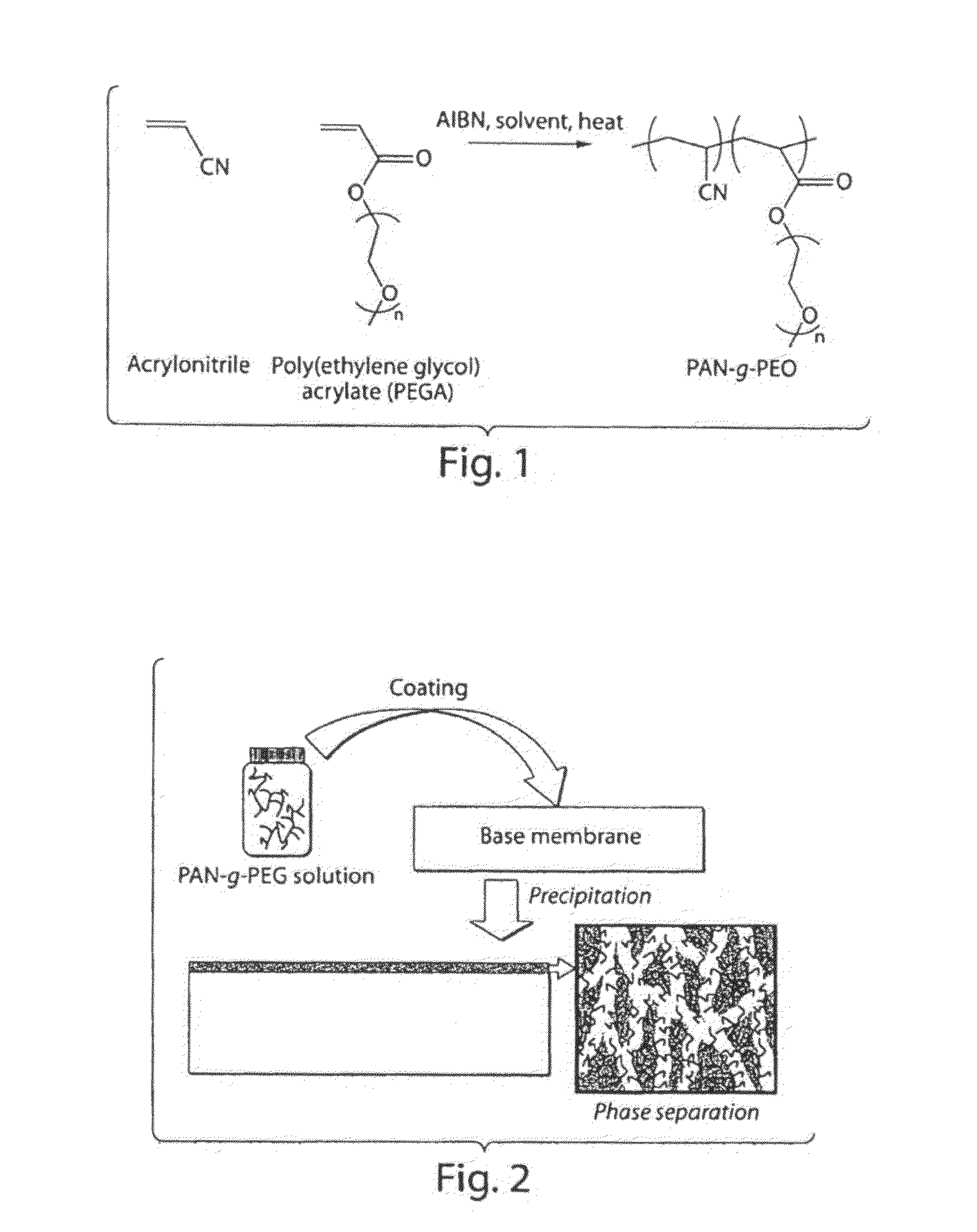
Synthesis of Polyacrylonitrile-graft-poly(ethylene glycol) (PAN-g-PEO) using Toluene as a Solvent

[0061]In this example, a graft copolymer with a PAN backbone and PEO side-chains, used in the preparation of certain membranes of the invention, was synthesized as follows. Acrylonitrile (Aldrich) and poly(ethylene glycol) methyl ether acrylate (PEGA) (454 g / mol, Aldrich) were passed through a column of basic activated alumina (VWR) to remove the inhibitor. Acrylonitrile (10 g, 188 mmol), PEGA (10 g, 22 mmol) and azobisisobutyronitrile (AIBN, 0.01 g, Aldrich) were dissolved in toluene (50 ml) in a round bottom flask. The flask was sealed. Nitrogen was bubbled through the reaction mixture with stirring for 20 minutes. The flask was then kept at 90° C. with stirring for 24 hours. The reaction mixture, which was observed to contain precipitated polymer, was then precipitated in hexane, and purified by stirring two fresh portions of hexane for several hours, followed by drying in the vacuum ...

example 2

Synthesis of Polyacrylonitrile-graft-poly(ethylene glycol) (PAN-g-PEO) using Dimethyl Formamide as a Solvent

[0063]In this example, acrylonitrile (Aldrich) and poly(ethylene glycol) methyl ether acrylate (PEGA) (454 g / mol, Aldrich) were passed through a column of basic activated alumina (VWR) to remove the inhibitor. Acrylonitrile (10 g, 188 mmol), PEGA (10 g, 22 mmol) and azobisisobutyronitrile (AIBN, 0.01 g, Aldrich) were dissolved in dimethyl formamide (DMF, 50 ml) in a round bottom flask. The flask was sealed. Nitrogen was bubbled through the reaction mixture with stirring for 20 minutes. The flask was then kept at 60° C. with stirring for 24 hours. The reaction mixture was then precipitated in a 1:1 mixture of hexane and ethanol, and purified by redissolving the polymer in DMF and reprecipitation in 1:1 hexane-ethanol mixture, followed by drying in the vacuum oven overnight. The composition of the white polymer obtained was calculated from the 1H-NMR spectrum, using the ratio of...

example 3

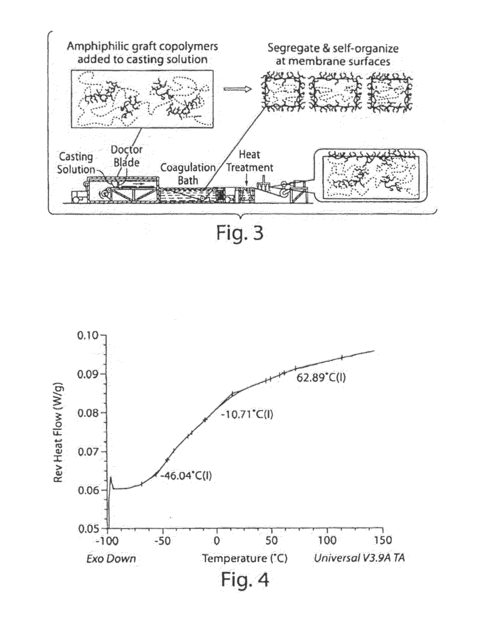
Microphase Separation Characteristics of PAN-g-PEO Samples with Different Casting Conditions

[0064]To observe the microphase separation characteristics of PAN-g-PEO, three different sets of samples were prepared for differential scanning calorimetry (DSC) testing in this example. DSC was done using a TA Instruments Q100 in modulated DSC (MDSC) mode so the kinetic effects could be removed from the obtained data and glass transitions could be observed more clearly through isolation of the reversible heat flow.

[0065]The first set of samples was aimed at simulating the conditions for membranes cast in isopropanol. For that, a glass microscope slide was covered with a thin layer of 20 wt % solution of PAN-g-PEO in DMF, so that approximately 0.3 ml of solution was spread over an area of 1.5 cm by 3 cm. The slide was then immersed in isopropanol for 30 minutes, followed by immersion in water for 10 minutes. The recovered transparent film detached from the glass and was dried in a vacuum ove...


PUM

PropertyMeasurementUnit
mean diameteraaaaaaaaaa
wt %aaaaaaaaaa
contact angleaaaaaaaaaa

Abstract

The present application is generally directed towards polyacrylonitrile- (PAN-) based, amphophilic graft copolymers, for example, for the production of membranes for liquid filtration. In one aspect, the present invention provides systems and methods for preparing high flux, fouling resistant nanofiltration membranes whose pore size can be readily tuned. In some cases, microphase separation of a graft copolymer comprising a backbone comprising polyacrylonitrile (PAN) and hydrophilic side-chains is used. In some cases, nanochannels of tunable width are formed, which may give the membrane permselective properties and / or anti-fouling character. In some cases, a copolymer may be used as an additive in the immersion precipitation casting of ultrafiltration or microfiltration membranes. In certain instances, the additive can segregate to the membrane exterior and / or pore surfaces, e.g., due to favorable interactions between the hydrophilic side chains and the surrounding environment, which may create a surface that resists fouling, e.g., by biological molecules.

Description

RELATED APPLICATIONS[0001]This application is a national-stage application under 35 U.S.C. §371 of International Patent Application No. PCT / US2007 / 008797, filed Apr. 10, 2007, entitled “Fouling Resistant Membranes Formed with Polyacrylonitrile Graft Copolymers,” by Mayes, et al., which claims priority to U.S. Patent Application Ser. No. 60 / 791,003, filed Apr. 11, 2006, entitled “Fouling Resistant Membranes Formed with Polyacrylonitrile Graft Copolymers,” by Mayes, et al., each of which is incorporated herein by reference.GOVERNMENT FUNDING[0002]Research leading to various aspects of the present invention were sponsored, at least in part, by the U.S. Navy, grant number N00014-02-1-0343, and the National Science Foundation, grant number CTS0120978. The U.S. Government has certain rights in this invention.FIELD OF THE INVENTION[0003]This invention is generally directed to polyacrylonitrile- (PAN-) based amphiphilic graft copolymers, which can be used in the production of membranes for ...

Claims


Application Information

Patent Timeline
Patent Type & Authority Patents(United States)
IPC IPC(8): B01D39/00B01D39/14B01D67/00C08F30/08
CPCB01D61/145B01D61/147B01D67/0093B01D69/02B01D71/42B01D71/78B01D2323/02B01D2325/20B01D2325/36B01D65/08B01D2321/16B01D2323/38B01D71/82
Inventor MAYES, ANNE M.ASATEKIN ALEXIOU, AYSE
Owner THE UNITED STATES OF AMERICA AS REPRESENTED BY THE SECRETARY OF THE NAVY
Why Eureka
Try Eureka