Soft silicone materials for ophthalmic applications

a technology of ophthalmic applications and silicone materials, applied in the field of polymer silicon materials, can solve the problems of damage to the corneal endothelium, adversely affecting the optical quality of the implant, and the foldable iols were not without drawbacks, and achieve high glass transition temperature and high glass transition temperature. , the effect of high glass transition temperatur

Active Publication Date: 2013-09-10
JOHNSON & JOHNSON SURGICAL VISION INC
View PDF32 Cites 11 Cited by
  • Summary
  • Abstract
  • Description
  • Claims
  • Application Information

AI Technical Summary

Benefits of technology

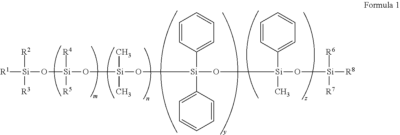
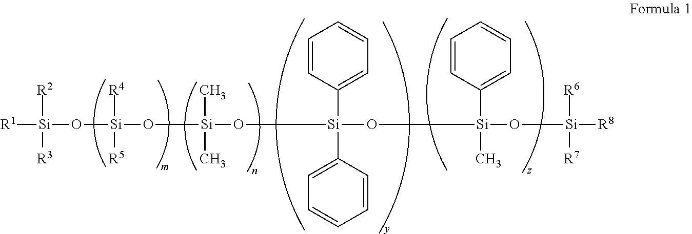
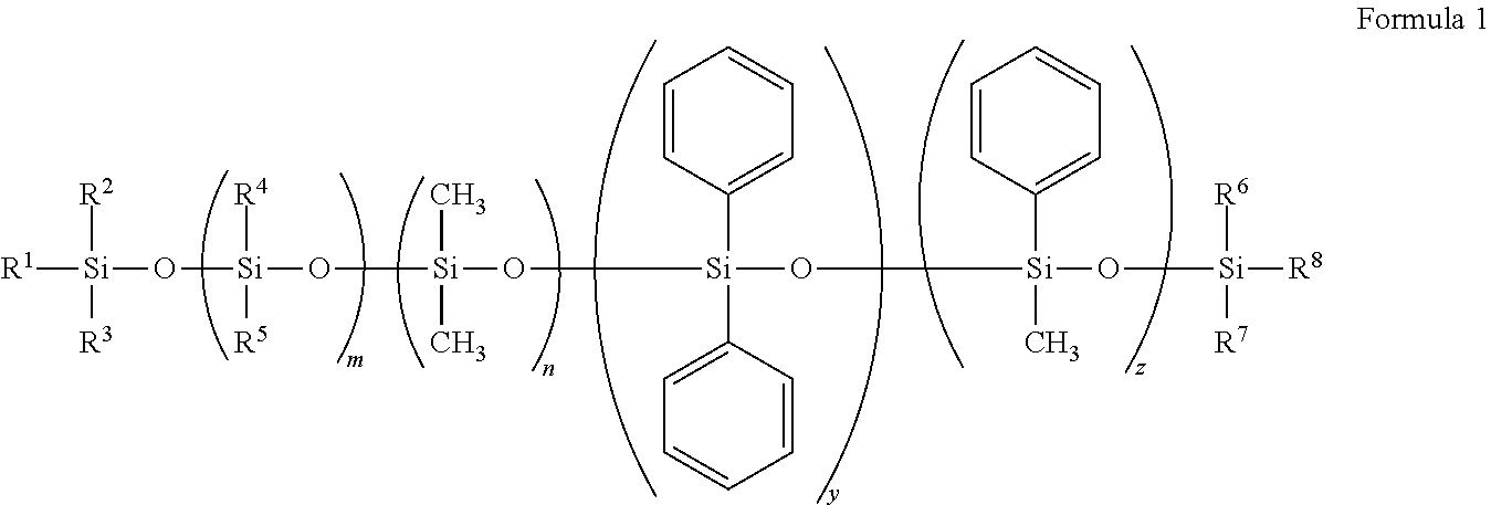
[0011]Described herein are silicone materials that posses relatively high glass transition temperatures (Tgs) when compared to conventional silicone materials. The silicone materials are formed from silicone fluids. In one embodiment, an increased Tg allows the formation of objects and materials by cryogenic lathing. The silicone materials, elastomers or gels can be formed by curing silicone fluid with a cross-linker mixture. The cross-linker mixture can comprise at least one cross-linker and at least one monofunctional hydride compound and when reacted with the silicone fluids described herein can form a silicone material that is soft and possesses a high glass transition temperature compared to existing silicone fluids. Upon formation, the silicone materials can be extracted over long periods of time without loss of optical quality. In one embodiment, upon formation, the silicon materials can have a sufficiently low amount of leachable content or can retain optical quality even after long extraction steps. Further, the silicone materials can be sufficiently soft allowing folding and insertion through small incisions in the eye. Additionally, methods of forming optical silicone materials and lenses, in general, are also disclosed. In one embodiment, the method of forming a lens comprising a silicone material using cryogenic lathing techniques is described.

Problems solved by technology

Occasionally, folding of the IOL before insertion resulted in permanent deformation, which adversely affected the implant's optical qualities.
Further, while foldable IOLs eliminated the need for the large incision, foldable IOLs were not without drawbacks.
In particular, both non-deformable and foldable IOLs are susceptible to mechanical dislocation resulting in damage to the corneal endothelium.
The primary drawback to this type of thermoplastic IOL is the limited number of polymers that meet the exacting needs of this approach.
Most polymers are composed of polymethylacrylate which have solid-elastomeric transition temperatures above 100° C. Modifications to the polymer substrate require the use of plasticizers that may eventually leach into the eye causing harmful effects.
However, once fully rehydrated, the polymer structure is notoriously weak due to the large amount of water absorbed.
At this water concentration the refractive index (RI) drops to about 1.36, which is unacceptable for an IOL since lower RI materials require the optic to be thicker to achieve a given optical power.
While pure acrylic IOLs have desirable mechanical, optical and biological properties, they may have unacceptable molecular response times such that the folded or compacted IOL may not unfold as quickly as desired.
A pure acrylate IOL fabricated to have a relatively fast molecular response time may be extremely tacky and lack the desired mechanical strength.
In this case, the resulting IOL may tear and / or the resulting self-tack can render unfolding difficult.
Presently, silicone polymeric materials used for optic soft gel implant applications suffer from an excess of leachable material resulting from a desire to keep the optic material from deforming during the manufacturing process.
This presents a danger to the patient as the leachable material can begin to leach immediately upon implantation into the eye.
However, each extraction causes lens material deformation and the need for remolding of the lens which comes at a great expense.

Method used


Image

  • Soft silicone materials for ophthalmic applications
  • Soft silicone materials for ophthalmic applications
  • Soft silicone materials for ophthalmic applications

Examples


example 1

Preparation of Polymers

[0101]A. Synthesis of a Hexavinyl Terminated Silicone Fluid without Pendent Vinyl Groups.

[0102]In a method for making this polymer (polymer B38), 103.48 grams of octaphenylcyclotetrasiloxane was placed in a preheated 1000 mL reaction kettle at 105° C. (±10° C.). The mechanical stirrer was turned on and the system was purged with nitrogen for at least 30 minutes. Next, 691.78 grams of octamethylcyclotetrasiloxane and 5.15 grams of hexavinyl dislioxane were added together to the reaction kettle. Then, 3.17 grams of tetramethylammonium siloxanolate was added to the reaction kettle. Stirring continued for at least 68 hours at 105° C. (±10° C.). The temperature of the kettle was then raised to 150° C. (±20° C.) for at least 5 hours. After cooling, the silicone fluid was filtered through a 0.2 micron filter.

[0103]B. Synthesis of a Hexavinyl Terminated Silicone Fluid with Pendent Vinyl Groups.

[0104]In a method for making this polymer (polymer B37), 129.35 grams of oc...

example 2

Preparation of Disc 1

[0111]In a vessel, 0.045 grams of platinum-cyclovinylmethylsiloxane complex, was added to 15 grams of the B38 0.25% UVAM silicone fluid. The mixture was well mixed by high speed centrifugation at least twice for 30 seconds. The resulting formed “Part A” of the silicone fluid. The final catalyst concentration of three otherwise identical silicone fluids was, by weight, about 0.1%, to about 0.5%. In a separate vessel, “Part B” of the silicone fluid was prepared by mixing 0.4038 grams of 25-30% methylhydrosiloxane-dimethylsiloxane copolymer, trimethylsiloxane terminated (HMS-301 from Gelest) with 5 grams of the B38 0.25% UVAM silicone fluid prepared above. Five grams of Part A and 5 grams of Part B were mixed in a vessel with a theoretical HN ratio=1.0.

[0112]The resulting silicone mixture was poured into a Teflon® mold and the mold was placed in an oven at 140° C. for 10 minutes. Moduli of these discs (before and after extraction) were measured using a Q800 DMA (TA...

example 3

Preparation of Disc 2

[0113]In a vessel, 0.045 grams of platinum-cyclovinylmethylsiloxane complex, was added to 15 grams of the B38 0.25% UVAM silicone fluid. The mixture was well mixed by high speed centrifugation at least twice for 30 seconds. In a separate vessel, “Part B” of the silicone fluid was prepared by mixing 0.0908 grams of phenyltris(dimethylsiloxy)silane and 5 grams of B38 0.25% UVAM silicone fluid. Five grams of Part A and 5 grams of Part B were mixed in a vessel with a theoretical HN ratio=0.5.

[0114]The resulting silicone mixture was poured into a Teflon® mold and the mold was placed in an oven at 140° C. for 10 minutes. Moduli of these discs (before and after extraction) were measured using a Q800 DMA (TA Instruments). Diameter and thickness of the sample was measured using a calibrator. After loading the sample on the holder, the temperature of the system was raised to 35° C. and held at equilibrium for 5 minutes before testing. Ramp force was applied to the disk at...


PUM

PropertyMeasurementUnit
Tgaaaaaaaaaa
refractive indexaaaaaaaaaa
solid-elastomeric transition temperaturesaaaaaaaaaa

Abstract

Described herein are silicone fluids and silicone materials that posses high glass transition temperatures (Tgs) when compared to conventional silicone materials. In one embodiment, an increased Tg allows the formation of objects and materials by cryogenic lathing. The fluids and materials can be formed by curing silicone fluid with a cross-linker mixture comprising a cross-linker and a monofunctional hydride compound. Upon formation, the silicone materials can be extracted over long periods of time without loss of optical quality. The silicone materials can be sufficiently soft allowing folding and insertion through small incisions in the eye. Additionally, methods of forming optical silicone materials, lenses and silicone materials in general are also disclosed. In one embodiment, the method of forming a silicone based lens using cryogenic lathing techniques is described.

Description

CROSS REFERENCE TO RELATED APPLICATIONS[0001]This application is a continuation-in-part of application Ser. No. 11 / 963,351 filed Dec. 21, 2007.FIELD OF THE INVENTION[0002]The present invention relates to polymeric silicon materials useful in forming optical materials including, but not limited to, lenses. Methods are also described for forming and shaping lenses.BACKGROUND OF THE INVENTION[0003]The use of polymeric materials for medical devices is an area where vast improvements in polymeric materials have evolved and are still evolving. Physical properties of these polymers can be fine tuned for use in different environments or to behave in a predictable manner. For example, polymers for use in fabricating intraocular lenses (IOLs), need adaptation allowing for smaller incisions during implantation as well as attain a lower level of leachable content in the polymeric material itself.[0004]Subsequently, IOLs were designed for smaller incisions through the use of elastomeric composit...

Claims


Application Information

Patent Timeline
Patent Type & Authority Patents(United States)
IPC IPC(8): C08G77/38
CPCC08G77/20G02B1/043C08L83/04A61F2/16A61F2002/16905
Inventor HU, CANPHAM, DEREK D.LOWERY, MICHAEL D.
Owner JOHNSON & JOHNSON SURGICAL VISION INC
Why Eureka
Try Eureka