Membrane catalytic heater

a catalytic heater and membrane technology, applied in the field of membrane catalytic heaters, can solve the problems of not teaching the application of the system to the catalytic combustion heater and not teaching the way to turn the device off, and achieve the effect of steady fuel delivery ra

Inactive Publication Date: 2013-11-19
GHT GLOBAL HEATING TECH
View PDF1 Cites 4 Cited by
  • Summary
  • Abstract
  • Description
  • Claims
  • Application Information

AI Technical Summary

Benefits of technology

[0006]The invention described herein refers to a portable catalytic heater in which fuel vapor and air (or other means of oxygen supply), are supplied to a catalyst. The catalyst promotes the flameless combustion of the fuel releasing heat. The liquid fuel is supplied through the use of a selectively permeable membrane, such that only the fuel vapors diffuse through the membrane and are fed to the catalyst. The catalyst is placed on a support that allows for the diffusion and mixing of reactants such as a porous fiber felt coated with catalysts. Alternatively, the selectively permeable membrane may support the catalyst. The supply of fuel to the selectively permeable membrane and the exact identity of the membrane serve as a way to regulate the degree of heating provided by the catalytic heater. The selective molecular filtration of the fuel through the membrane keeps the catalytic heater from being contaminated from impurities in the fuel, such as salts. The selective permeability of the membrane to fuels (e.g. methanol), over the product (i.e. water), keeps the liquid fuel reservoir from being contaminated with the product and maintains the fuel concentration and a steady rate of fuel delivery. By containing the fuel behind the selective membrane and using diffusion to deliver the fuel, the rate is dependent upon the concentration of liquid in contact with the fuel membrane rather than the fuel vapor pressure. This makes the delivery of fuel and air to the catalyst less sensitive to temperature.
[0007]Another feature of the invention is an additional coating which protects the combustion catalyst from contamination and can enhance the catalytic effects. If the coating has the ability to conduct ions (i.e. protons), it may be used to enhance or lower the catalytic combustion rate through electrochemical processes on the catalysts (removal / addition of hydrogen / proton intermediates to catalytic surface). This may be achieved by inserting two electrodes on either side of the coating and applying a voltage across said coating. The coating also has certain permeability to the fuel and the products of the combustion reaction. It serves the purpose of adhering the catalyst powders to the substrate on which they are supported and can limit the catalytic combustion rate serving as yet another regulating mechanism in our invention. The coating can also have an affinity for the fuel, oxidizer, and products to increase the effectiveness of the fuel. The catalytic heater can be incorporated into a system for various applications. One of the unique features of using a liquid fuel with the selectively permeable membrane in proximity to the catalytic heater is when the fuel reaches its boiling point it removes heat from the catalytic reaction site and subsequently limits the maximum temperature. The vaporized fuel can be condensed in a heat exchanger and deliver the thermal output of the heater efficiently. Different mixtures of fuels or a maximum pressure of the fuel reservoir can be chosen to set the boiling point of the fuel and hence the maximum temperature of the heater. This fuel boiling mechanism along with the back diffusion of carbon dioxide and nitrogen can also be used to keep the fuel homogeneous and self purging. By keeping the fuel homogeneous and not in direct contact with catalysts the heater can easily be purged of fuel contamination by draining the fuel.
[0010]Additional features of this invention are the pressurization of the fuel behind the selectively permeable membrane and its flexibility which enable unique passive controls of the diffusion of fuel and air. Temperature selective diffusion through the membrane can also be used to limit or accelerate the fuel delivery. Also, the flexibility of the polymers and rubber materials used in this invention permits flexibility in packaging into a wide variety of applications such as apparel, blankets, machinery, dwellings, shipping containers, storage containers, insect attractants, humidifiers, and perfume generators.PRIOR ART

Problems solved by technology

It does not teach the application of the system to a catalytic combustion heater.
It does not cover means of regulating the amount of heat using permeable membranes, and it does not teach how to turn the device off.

Method used


Image

  • Membrane catalytic heater
  • Membrane catalytic heater
  • Membrane catalytic heater

Examples


Embodiment Construction

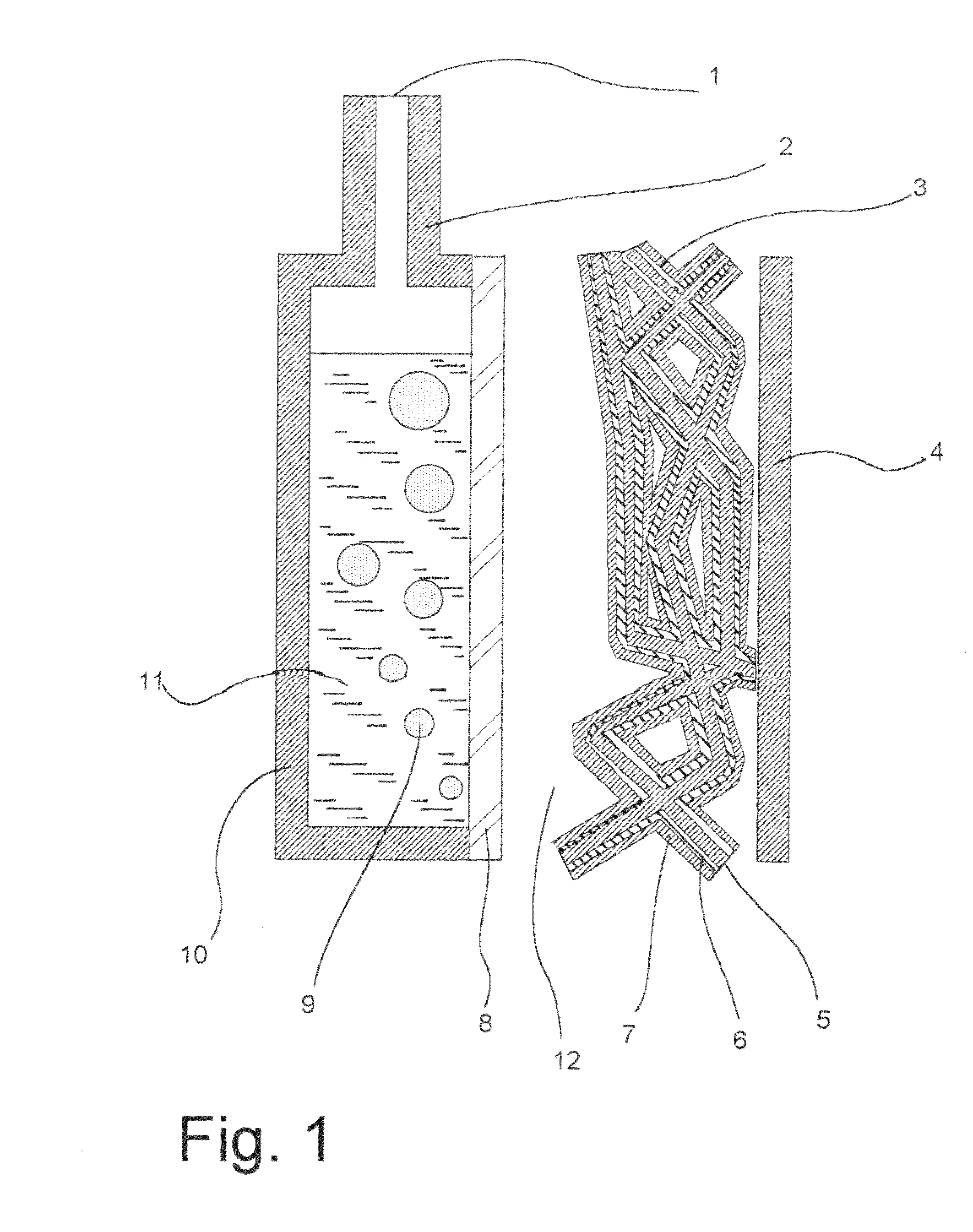
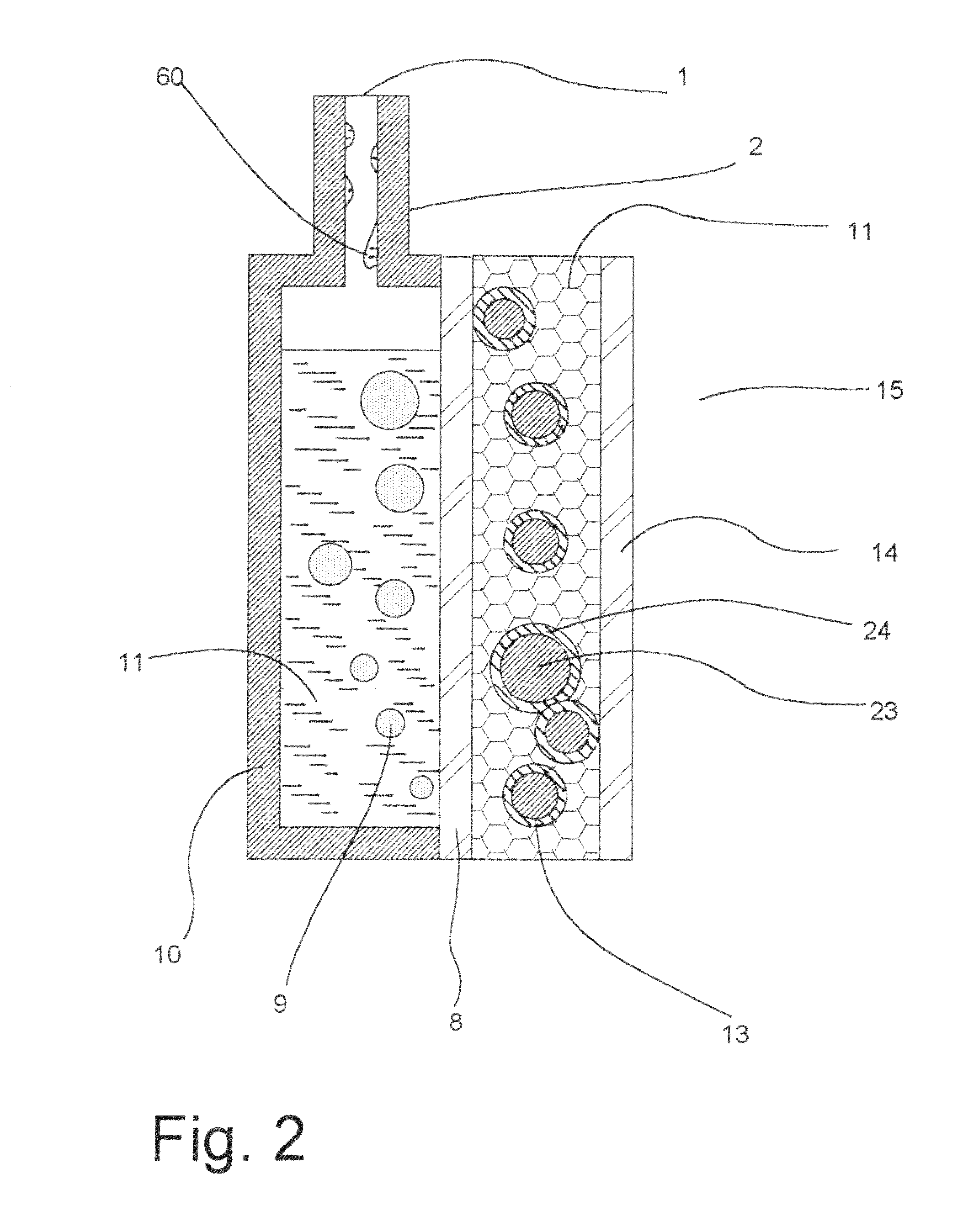
[0031]In FIG. 1 a fuel tank 10 is shown filled with methanol fuel 11. The aluminum tank 10 has a silicone rubber membrane 8 (Specialty Silicone Products, Corporate Technology Park, 3 McCrea Hill Road, Ballston Spa, N.Y. 12020) sealed to the tank wall with 100% silicone rubber sealant (GE Silicones, Waterford, N.Y. 12188); The methanol fuel 11 preferentially diffuses through the silicone rubber membrane 8 to mix with air 12. Several alternative fuels 11 are formaldehyde, formic acid, 1,3,5-trioxane, di-methyl-ether, acetone and pentane, among others. A felt of polybenzoxazole (PBO), a high temperature high performance fiber 5 (Zylon felt, Toyobo, 2-8, Dojima Hama 2-Chome, Kita-Ku, Osaka, 530-8230, Japan) is coated with Platinum and Ruthenium (Pt / Ru) black catalyst 6 (Alfa-Aesar Alfa-Aesar 30 Bond Street Ward Hill, Mass. 01835-8099). Alternative felts are made of fibers of polybenzimidazole (PBI), polyimides, alumina, fiber glass, zirconia, quartz, p-aramids felts. This catalyst layer...


PUM


Abstract

A portable catalytic combustion heater, wherein fuel vapor (11) and air (10) are supplied to a catalyst (6) which promotes the flameless combustion of fuel and releases that. The fuel is supplied as a liquid, passes through a selectively permeable membrane (8) such as fuel vapor exits the membrane and is fed to the catalyst (6). Additional features include porous supports and means of enhancing and diminishing the catalytic rate of combustion and controlling the heat output.

Description

[0001]This application is a division of application Ser. No. 10 / 492,018, filed Apr. 8, 2004, now U.S. Pat. No. 7,708,553, issued May 4, 2010, which claims the benefit of U.S. Provisional Application No. 60 / 327,310, filed Oct. 9, 2001 and PCT US02 / 32041, filed Oct. 9, 2002, all of which are hereby incorporated by reference in their entireties as if fully set forth herein.BACKGROUND OF THE INVENTION[0002]Flameless combustion heaters are well known. They typically work on the principle that an appropriate hydrocarbon-based fuel, when in contact with a suitable catalyst in the presence of air (or oxygen), will undergo combustion and release heat. This heat can then be distributed and used for a variety of purposes.[0003]A variety of patents describe the incorporation of such a device on a garment such as a jacket or a belt for providing heat to the body. They typically describe means of pumping the fuel, preheating the fuel-air mixture (often by ignition), and controlling the feeding of...

Claims


Application Information

Patent Timeline
Patent Type & Authority Patents(United States)
IPC IPC(8): F23D3/40F23C13/00F23D14/18
CPCF23C13/00F23C13/02F23C13/08F23D14/18F23D2900/03081F23N2037/12F23N2037/14F23N2237/12F23N2237/14Y02E20/34
Inventor HOCKADAY, ROBERT G.TURNER, PATRICK S.BRADFORD, ZACHARY R.DEJOHN, MARC D.NAVAS, CARLOS J.VAZ, HEATHCLIFF L.
Owner GHT GLOBAL HEATING TECH
Why Eureka
Try Eureka