
Integrated circuits for high speed adaptive compression and methods therefor

a high-speed adaptive compression and integrated circuit technology, applied in the field of data optimization engines, can solve the problems of limiting the overall system performance, the clock speed of a typical data or address bus, and the inability to run these buses at a higher speed to match, etc., and achieve the effect of high speed

Active Publication Date: 2014-01-28
CHARTOLEAUX
View PDF38 Cites 18 Cited by
  • Summary
  • Abstract
  • Description
  • Claims
  • Application Information

AI Technical Summary

Benefits of technology

This patent describes a method for compressing data using a Content-Addressable-Memory (CAM) array and a shadow RAM. This approach allows for fast data compression. The patent also mentions that the integrated circuit implementing this compression technique may have multiple CAM arrays that are used to store codebooks associated with consecutive data files. This helps to ensure that one CAM is always ready to store the codebook of the next input file. Overall, this patent describes a speedy and efficient way to compress data using CAM and shadow RAM.

Problems solved by technology

In modern high-speed electronic systems, the data transmission link has long been regarded as one of the bottlenecks that limit overall system performance.
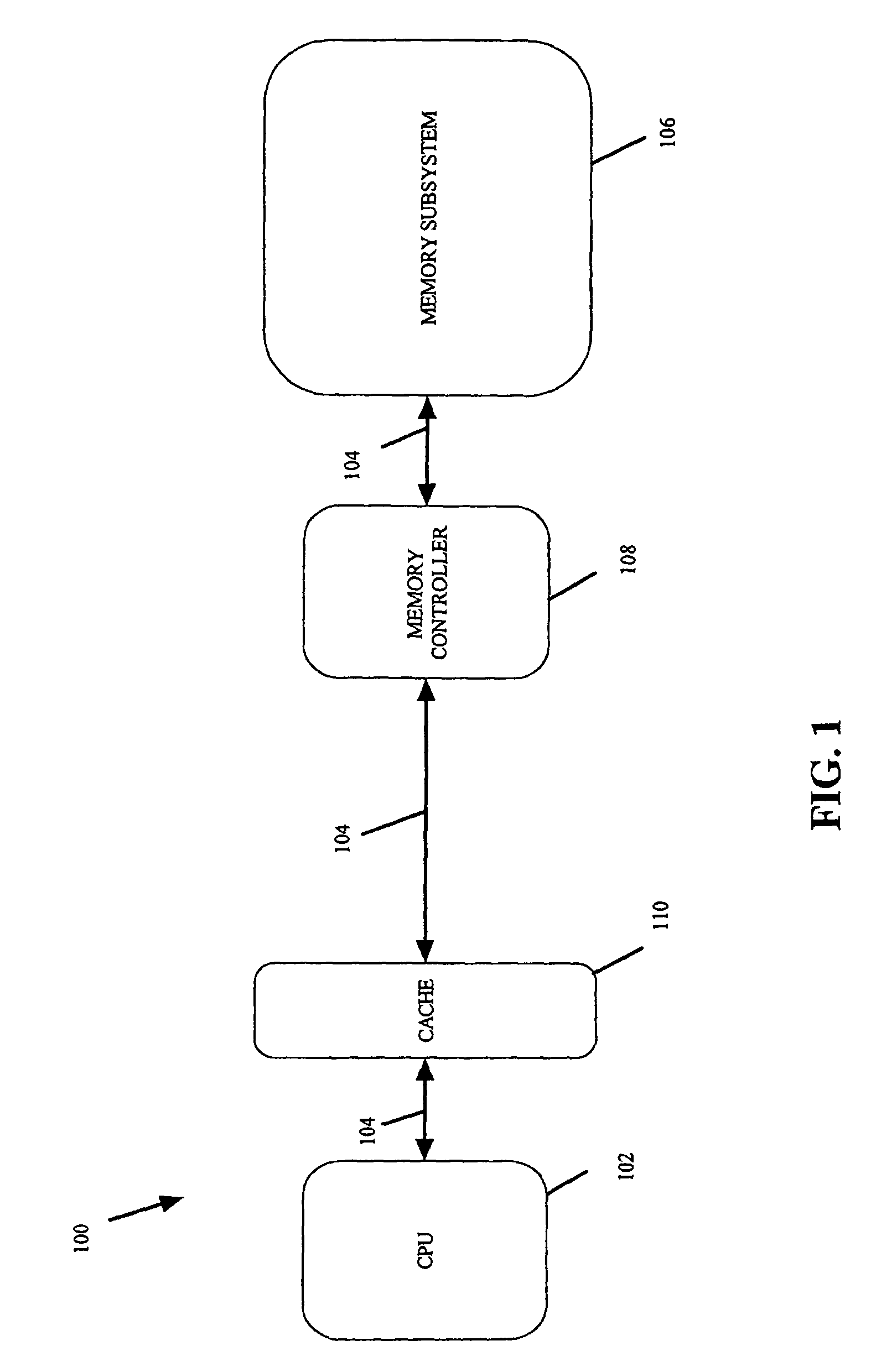
The clock speed of a typical data or address bus, on the other hand, is limited by the impedance and other physical characteristics of conductive traces that comprise the bus.
Thus, it is often times impractical to run these buses at a higher speed to match the speed of the fast CPU due to issues related to power, interference, and the like.
Together, these factors tend to limit the speed of a typical DRAM to well below the operating speed of the CPU.
Caching, however, increases the overall complexity of the computer system architecture and its operating system.
Further, the use of expensive and power-hungry cache memory (e.g., on-board high speed custom SRAM) disadvantageously increases cost, power consumption, and the like.
If the cache hit rate is low, there may not be a significant improvement in memory access speed to justify the added complexity and cost of a cache subsystem.
Modern complex software, which is often employed to manipulate large database, graphics, sound, or video files, requires a large amount of main memory space for optimum performance.
Due to power consumption, board space usage, and cost concerns, however, most computer systems are however manufactured and sold today with a less-than-optimum amount of physical memory on board.
Consequently, the overall system performance suffers.
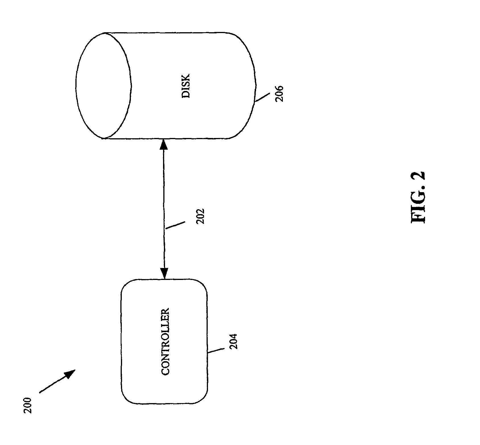
When a hard disk drive is employed for storing data, for example, the limited speed of the data transmission link between the hard disk drive and the main system bus, the slow access time due to the mechanical rotation nature of the hard disk's platters and the mechanical movement of the actuator arm that contains the read / write head, as well as the fixed storage capacity of the platters all represent factors that tend to limit system performance.
The data transmission bandwidth bottleneck also exists within modern high-speed computer networks, which are widely employed for carrying data among networked devices, whether across a room or across a continent.
In these devices, the line cards and / or switch fabric are configured to operate at a fixed speed, which is typically limited by the speed of the constituent devices comprising the line card.
In some cases, the bottleneck may be with the protocol employed to transmit the data among the various networked devices.
Accordingly, even if the transmission media itself (such as a fiber optic) may theoretically be capable of carrying a greater amount of data, the hardware, software, and transmission protocols may impose a hard limit on the amount of data carried between two nodes in a computer network.
A hardware upgrade to one of the higher speed protocols, unfortunately, tends to involve network-wide disruptive changes (since the sending and receiving network nodes must be upgraded to operate at the same speed).
A system-wide upgrade is also costly as many network nodes and components must be upgraded simultaneously to physically handle the higher speed protocol.
As mentioned, some incoming data frames may be non-optimizable, e.g., due to an explicit request from software or from some other higher layer in the communication stack.

Method used


Image

  • Integrated circuits for high speed adaptive compression and methods therefor
  • Integrated circuits for high speed adaptive compression and methods therefor
  • Integrated circuits for high speed adaptive compression and methods therefor

Examples


Embodiment Construction

[0046]The present invention will now be described in detail with reference to a few preferred embodiments thereof as illustrated in the accompanying drawings. In the following description, numerous specific details are set forth in order to provide a thorough understanding of the present invention. It will be apparent, however, to one skilled in the art, that the present invention may be practiced without some or all of these specific details. In other instances, well known process steps and / or structures have not been described in detail in order to not unnecessarily obscure the present invention.

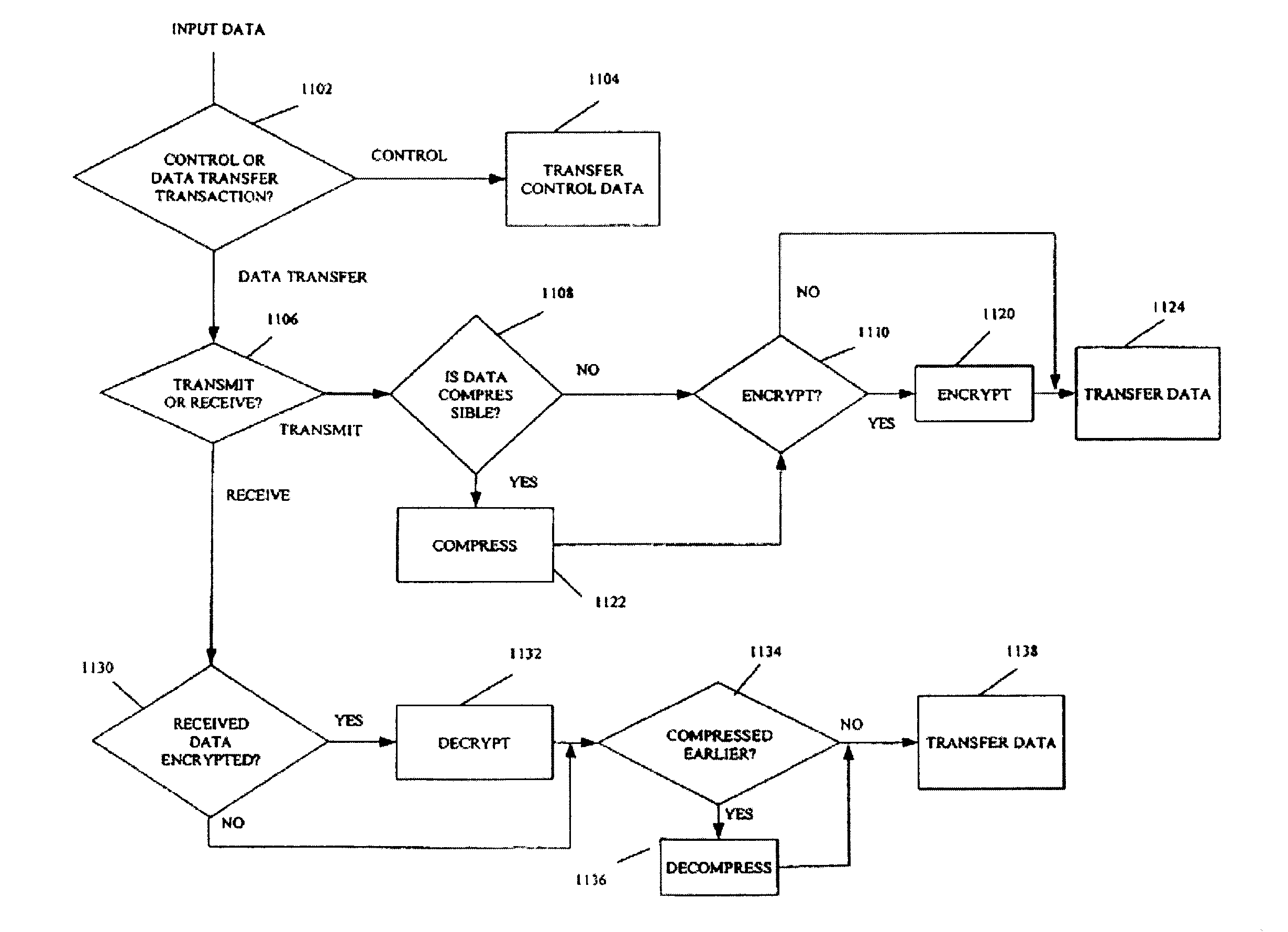
[0047]FIG. 4 shows, in accordance with one embodiment of the present invention, a high level block diagram of the inventive data optimization engine 400. Referring now to FIG. 4, the inventive data optimization engine includes three main logic blocks in each of the transmit and receive data paths. In the transmit data path, data input at a bus 402 is received by a protocol recognition engi...


PUM


Abstract

A computer-implemented method for compressing a first stream of data, the first stream of data comprising a plurality of input words. The computer-implemented method includes receiving the plurality input words, and adaptively compressing the plurality of input words into a plurality of compression codes. The computer-implemented method further includes outputting the plurality of compression codes upon encountering an end-of-file signal in the first stream of data, wherein the plurality of compression codes are fewer in number than the number of unique bit patterns requiring unique compression codes under LZW (Lempel Ziv & Welch) compression.

Description

[0001]This application is a divisional of U.S. application No. 10 / 026,680, filed on Dec. 17, 2001, now abandoned, which is incorporated herein by reference.BACKGROUND OF THE INVENTION[0002]The present invention relates to a data optimization engine for optimizing data transmission bandwidth and storage capacity in electronic systems and computer networks. More particularly, the present invention relates to highly modular data optimization engines, which are designed to be reconfigurable in an efficient and simplified manner to work with different protocols, and methods therefor.[0003]Data transmission links and data storage devices are basic building blocks of modern electronic systems and computer networks. Data transmission links are present in every electronic system and are also fundamental for interconnecting nodes in a computer network. In an electronic system, such as in a computer for example, a data transmission link such as an address bus or a data bus may be employed to t...

Claims


Application Information

Patent Timeline
Patent Type & Authority Patents(United States)
IPC IPC(8): G06F15/16
CPCH03M7/3088H03M7/30
Inventor ACHLER, ISAAC
Owner CHARTOLEAUX
Learn More