Laser optical system using optical fiber transmission

a laser optical system and optical fiber technology, applied in the field of laser optical systems, can solve the problems of significant energy loss, increased risk of damage with an increase in the energy density of the input laser light, and damage to optical fiber, and achieves the effects of high output, improved performance of laser oscillators, and improved optical fiber

Active Publication Date: 2014-03-04
THE JAPAN STEEL WORKS LTD +1
View PDF8 Cites 10 Cited by
  • Summary
  • Abstract
  • Description
  • Claims
  • Application Information

AI Technical Summary

Benefits of technology

[0006]The performance of laser oscillators is improving progressively, and some of the laser oscillators now on the market are capable of producing extremely high outputs. When an optical fiber is connected to the output end of a high output laser oscillator, the optical fiber could be damaged. Such damage typically occurs at the input end of the optical fiber, and the risk of damage increases with an increase in the energy density of the input laser light. The density of the laser light in the optical fiber can be reduced by increasing the core diameter of the optical fiber. In other words, the energy density of the output laser light can be reduced by converging the laser light by using an optical fiber having a core diameter great enough for the given output of the laser oscillator.
[0007]On the other hand, the laser system designed for the purposes of annealing and optical exposure is desired to be able to produce laser light of a high energy density because a high energy density means a higher throughput and a lower cost for each annealed product. Therefore, it is desired to shape the cross section of the laser beam into a linear shape in addition to increasing the lengthwise dimension of the linear cross section in view of increasing the energy density of the laser beam and allowing a large surface area to be processed in a short period of time.
[0008]When an attempt is made to reduce the width of the cross section of the laser beam with the aim of increasing the throughput by means of a higher energy density, depending on the exit angle of the laser beam emitted from the optical fiber, the optical magnification factor may exceed the limit imposed by Abbe's diffraction theory, and this will result in a significant energy loss. Furthermore, the core diameter is required to be increased in order to avoid damage to the optical fiber so that the laser beam emitted from the laser oscillator could not be shaped into a linear beam with a cross section having an adequately small width.
[0011]Owing to this arrangement, the laser light emitted from the first optical fiber is converged into a plurality of spots by using the array lens, and then transmitted to the second optical fibers whose output ends are arranged in a single row so that the damage to the first optical fiber can be avoided by increasing the core diameter of the first optical fiber and a linear beam having a large lengthwise dimension as compared to the widthwise dimension can be obtained. By suitably changing the number of cells of the array lens and the number of the second optical fibers, the widthwise dimension of the linear beam can be selected at will.
[0015]Owing to this arrangement, the laser light emitted from the first optical fiber can be introduced into the second optical fibers with a minimum energy loss so that a linear beam of a high intensity (high energy density) can be obtained.
[0019]According to the present invention, the laser light emitted from the optical fibers can be shaped into a linear beam having a small widthwise dimension with a minimum energy loss.

Problems solved by technology

When an optical fiber is connected to the output end of a high output laser oscillator, the optical fiber could be damaged.
Such damage typically occurs at the input end of the optical fiber, and the risk of damage increases with an increase in the energy density of the input laser light.
When an attempt is made to reduce the width of the cross section of the laser beam with the aim of increasing the throughput by means of a higher energy density, depending on the exit angle of the laser beam emitted from the optical fiber, the optical magnification factor may exceed the limit imposed by Abbe's diffraction theory, and this will result in a significant energy loss.
Furthermore, the core diameter is required to be increased in order to avoid damage to the optical fiber so that the laser beam emitted from the laser oscillator could not be shaped into a linear beam with a cross section having an adequately small width.

Method used


Image

  • Laser optical system using optical fiber transmission
  • Laser optical system using optical fiber transmission
  • Laser optical system using optical fiber transmission

Examples


Embodiment Construction

[0024]Now the present invention is described in the following in more detail in terms of a concrete embodiment with reference to the appended drawings.

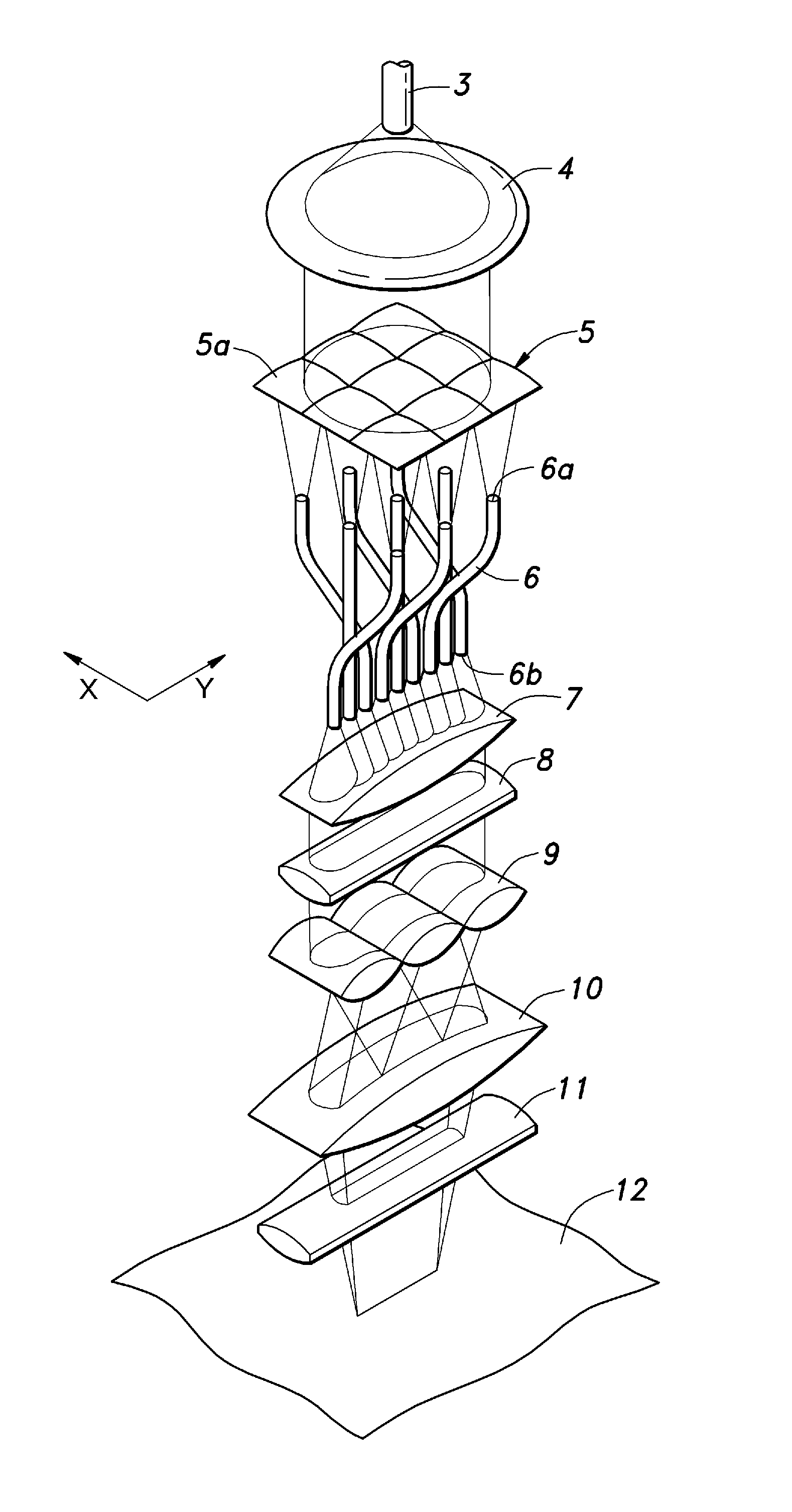
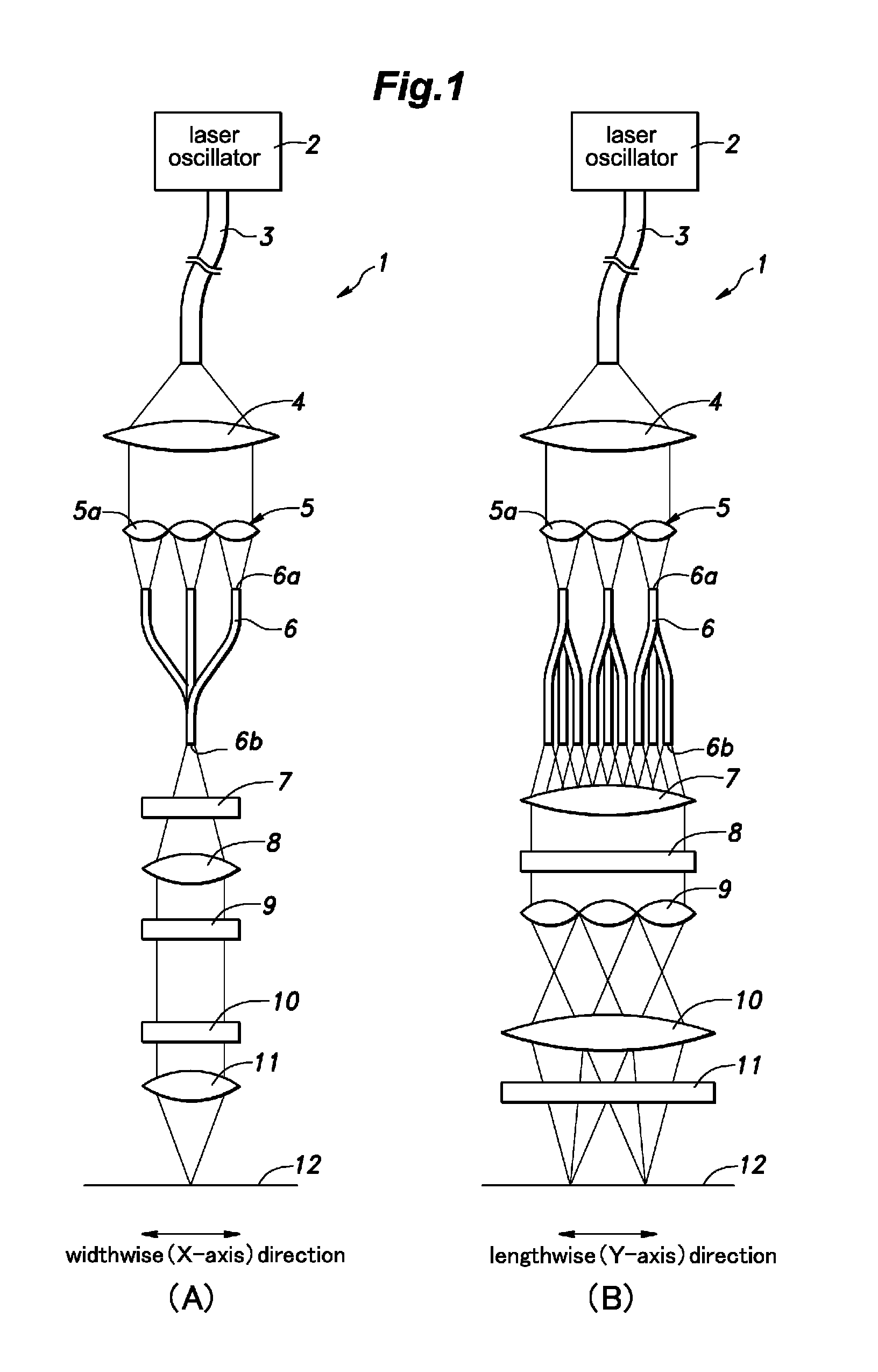
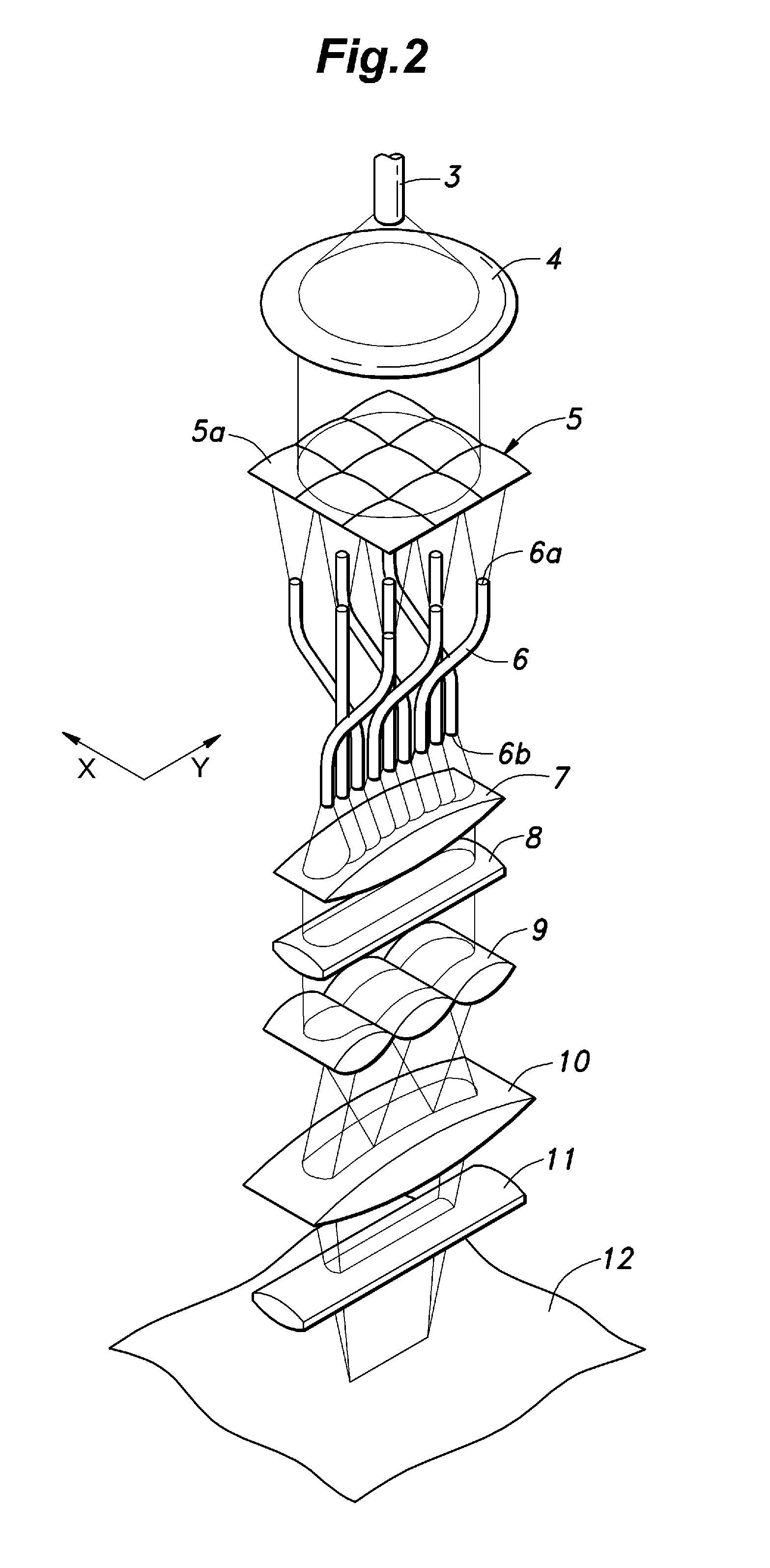
[0025]FIG. 1 is a schematic diagram of a laser optical system 1 using optical fibers for transmitting laser light embodying the present invention. In particular, FIG. 1(A) shows a front view of the optical system, and FIG. 1(B) shows a side view of the optical system. As shown in FIGS. 1 and 2, the laser optical system 1 includes a laser oscillator 2 having a first optical fiber 3 connected to a laser output end thereof. The first optical fiber 3 is provided with a relatively large core diameter which is large enough to avoid damage to the first optical fiber 3 when subjected to the laser light emitted from the laser oscillator 2, and emits laser light having a prescribed divergent cone angle from an output end thereof. To the output end of the first optical fiber 3 is disposed a collimator lens 4 which transforms the laser light emit...


PUM

PropertyMeasurementUnit
core diameteraaaaaaaaaa
diameteraaaaaaaaaa
surface areaaaaaaaaaaa

Abstract

A laser optical system using optical fiber transmission, includes a first optical fiber for transmitting laser light emitted from a laser oscillator, a collimator lens for collimating laser light emitted from the first optical fiber, a spherical array lens including a plurality of cells for converging laser light emitted from the collimator lens into a plurality of spots, a plurality of second optical fibers each having a smaller core diameter than the first optical fiber and configured to admit the laser light converged into the corresponding spot by the spherical array lens, the second optical fibers having output ends that have mutually parallel axial lines and are arranged linearly in a single row, and a linearization optical unit for shaping laser light emitted from the second optical fibers into laser light having a linear cross section at an illuminated surface.

Description

TECHNICAL FIELD[0001]The present invention relates to a laser optical system using optical fibers for transmitting laser light generated from an oscillator and shaping the laser light into a prescribed laser beam, and in particular to a laser optical system suitable for use in annealing silicon thin film.[0002]The laser annealing technology is known as a technology for crystallizing or otherwise modifying the surface of a work piece by using laser light. The conventional laser annealing system typically consisted of an excimer laser using a laser oscillator configured to produce a laser beam having a linear or rectangular cross section. Laser annealing systems using an excimer laser are proposed in Patent Documents 1 and 2. Such conventional systems normally used arrays of cylindrical lens arranged in a mutually perpendicular relationship to shape the laser light emitted from a laser oscillator into a laser beam having a uniform intensity distribution along a certain cross sectional...

Claims


Application Information

Patent Timeline
Patent Type & Authority Patents(United States)
IPC IPC(8): G02B6/36B23K26/064B23K26/073H01L21/20H01L21/268
CPCB23K26/0652B23K26/0676B23K26/0648H01L21/268G02B6/0006H01L21/02678B23K26/0738G02B27/30G02B6/0008H01L21/324
Inventor YAHATA, TOMONARIAIDA, YOSHIAKITOGASHI, RYOTAROSATO, RYOSUKEINAMI, TOSHIOKUSAMA, HIDEAKI
Owner THE JAPAN STEEL WORKS LTD
Why Eureka
Try Eureka