Eureka AIR delivers breakthrough ideas for toughest innovation challenges, trusted by R&D personnel around the world.

Metal enhanced fluorescence from metallic nanoburger structures

a dielectric material and enhanced fluorescence technology, applied in the direction of fluorescence/phosphorescence, luminescent dosimeters, optical radiation measurement, etc., can solve the problem of not being able to provide different layer sizes or components within such layers, and achieve the effect of increasing fluorophore photostability, reducing lifetime, and increasing fluorescence intensity

Active Publication Date: 2014-05-13
UNIV OF MARYLAND BALTIMORE COUNTY
View PDF45 Cites 18 Cited by
  • Summary
  • Abstract
  • Description
  • Claims
  • Application Information

AI Technical Summary

Benefits of technology

[0007]The present invention provides for structures of metallic nanoparticle layer / dielectric layer / metal metallic nanoparticle layer that exhibit several distinctive properties including significantly enhanced intensity of fluorescence, decreased lifetime and increased fluorophore photostability. Notably, dielectric materials may include any material that acts as an insulator, restricts movement of electrons therewithin and preferably has a dielectric constant greater than three (3). Such dielectrics may include solid materials such as metal oxides; organic polymers such as epoxy and nylon, polyvinyl chloride (pvc);
[0008]The thickness of the metal oxide, dielectric layer or optical coating can be varied while maintaining the consistency of the metallic particle layers thereby providing an electric field intensity that can be tuned by varying the distance between the metallic particles.
[0035]c) contacting the bound target molecule with the free biomolecular probe, wherein binding of the free biomolecular probe to the target molecule causes the fluorophore to be positioned a sufficient distance from the immobilized metallic structures to enhance fluorescence emission when excited by an irradiating source.

Problems solved by technology

However, these studies have for the most part been focused on one SIF layer14, 34-36 and thus provide no ability to provide different layer sizes or components within such layers to provide tunable responses from the SIFs.

Method used


Image

  • Metal enhanced fluorescence from metallic nanoburger structures
  • Metal enhanced fluorescence from metallic nanoburger structures
  • Metal enhanced fluorescence from metallic nanoburger structures

Examples


examples

Method and Materials

[0103]FITC (Fluorescein Isothiocyanate) was obtained from the Sigma-Aldrich Chemical company and used as received. Silane Prep™ glass microscope slides were purchased from Sigma-Aldrich.

[0104]Preparation of Nanoburger Substrates for Metal-Enhanced Fluorescence (MEF) Measurements

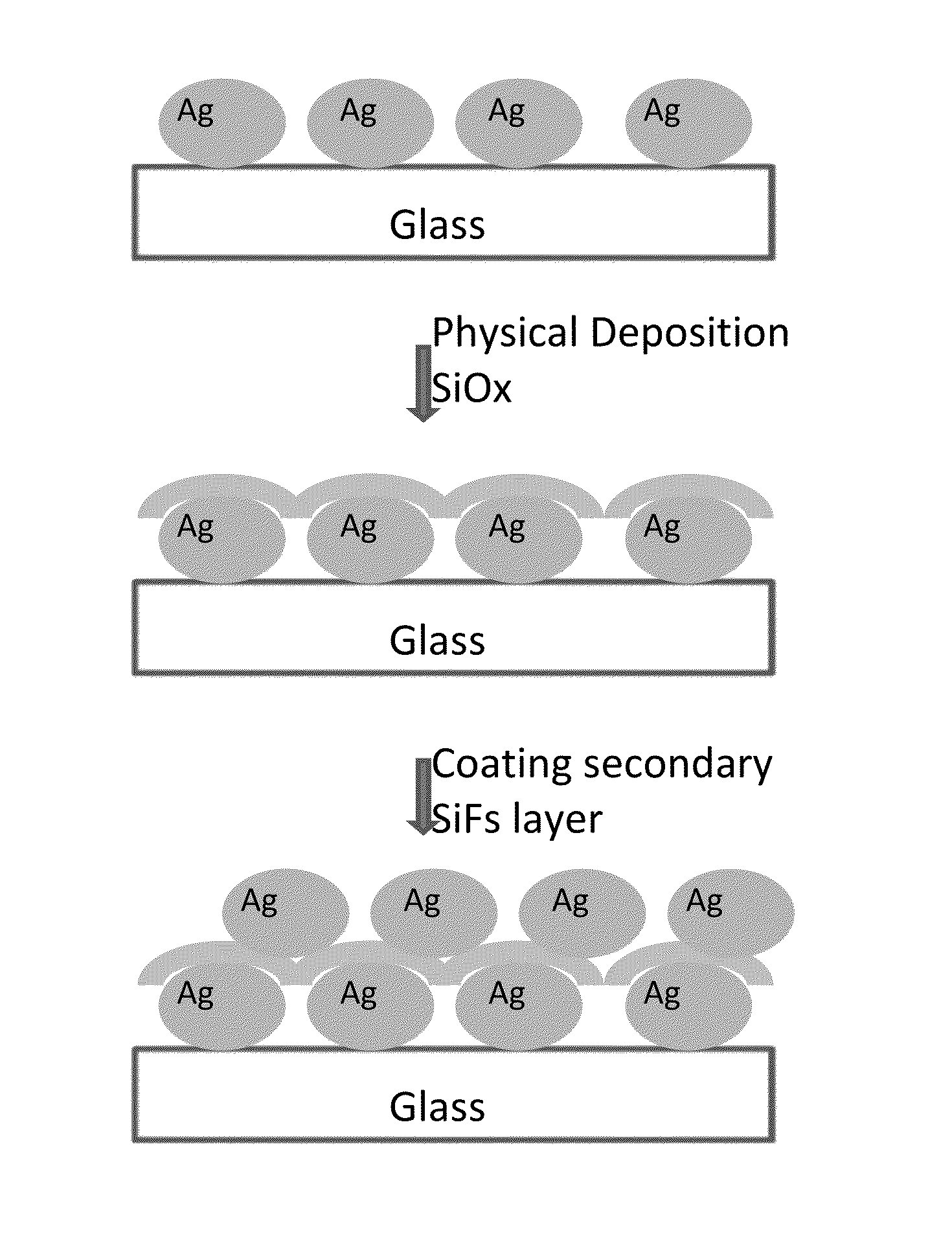
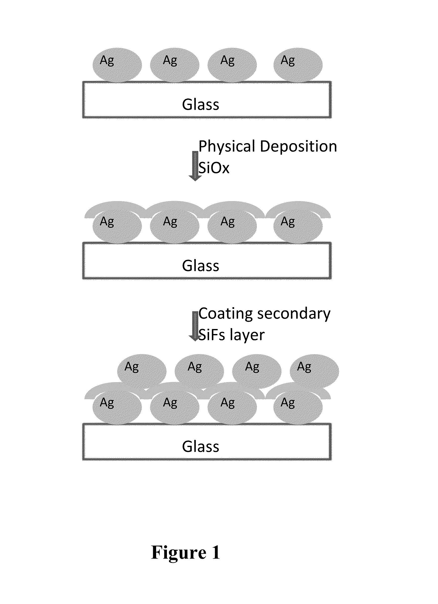
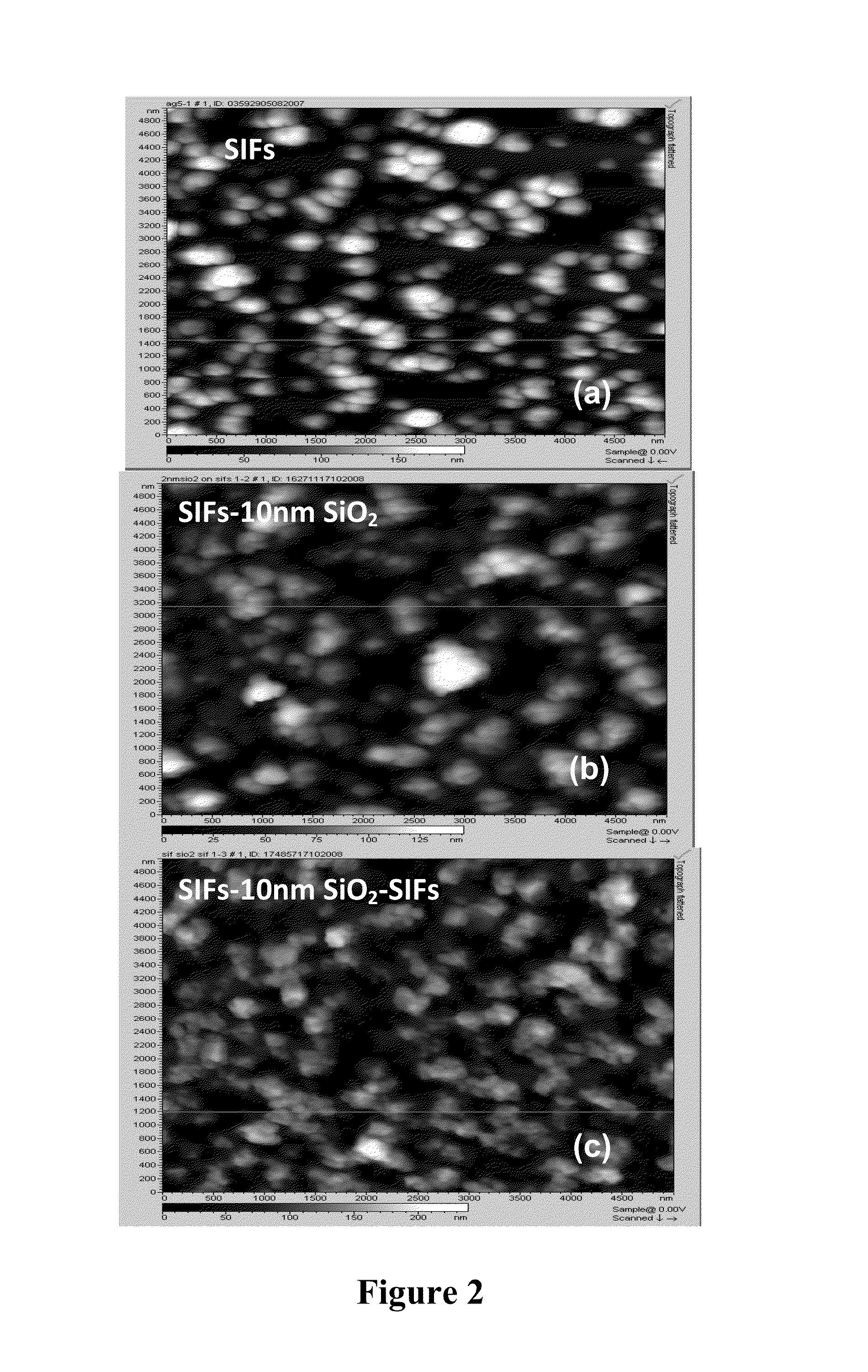
[0105]The schematic of the SIFs nanoburger surface preparation is shown in FIG. 1. It includes three layers. The first layer is a silver film (SIF). SIFs were prepared as previously published.39 In a typical SIFs preparation, a solution of silver nitrate (0.5 g in 60 ml of deionized water) was prepared in a clean 100-mL glass beaker. 200 μL of freshly prepared 5% (w / v) sodium hydroxide solution and 2 ml of ammonium were added to a continuously stirred silver nitrate solution at room temperature. Subsequently, the solution was cooled to 5° C. by placing the beaker in an ice bath, followed by soaking the Silane-Prep™ glass slides in the solution and adding a fresh solution of D-glucose (0.72...


PUM

PropertyMeasurementUnit
thicknessaaaaaaaaaa
thicknessaaaaaaaaaa
thicknessaaaaaaaaaa

Abstract

The present invention provides for metallic nanostructures or nanoburgers comprising a dielectric layer positioned between metallic layers and their use in metal enhanced emissions systems to enhance emissions from fluorophores, including intrinsic and extrinsic; luminophores; bioluminescent species and / or chemiluminescent species. The multilayer nanoburgers exhibit several distinctive properties including significantly enhanced intensity of emissions, decreased lifetime and increased photostability by simply varying the thickness of the dielectric layer while maintaining a constant thickness of the two metallic layers on opposite sides of the dielectric layer.

Description

CROSS-REFERENCE TO RELATED APPLICATIONS[0001]This application is filed under the provisions of 35 U.S.C. §371 and claims the priority of International Patent Application No. PCT / US2010 / 057946 filed on Nov. 24, 2010, which in turn claims priority to U.S. Provisional Patent Application No. 61 / 264,645 filed on Nov. 25, 2009, the contents of which are hereby incorporated by reference herein for all purposes.BACKGROUND OF THE INVENTION[0002]1. Field of the Invention[0003]The present invention relates to metallic nanostructures, and more particularly, to layered structures comprising a dielectric material layer positioned between metallic layers and their use in metal enhanced emissions systems to enhance emissions from fluorophores, including intrinsic and extrinsic fluorophores; luminophores; bioluminescent species and / or chemiluminescent species.[0004]2. Background of the Related Art[0005]Fluorescence detection is an important tool in medical diagnostics high-throughput screening, micr...

Claims


Application Information

Patent Timeline
Patent Type & Authority Patents(United States)
IPC IPC(8): G01N33/553G01N21/55G01N33/543
CPCG01N33/54346G01N21/6408G01N21/648G01N21/554G01N21/64B82Y15/00G01N33/553G01N33/54353Y10T428/256
Inventor GEDDES, CHRIS, D.
Owner UNIV OF MARYLAND BALTIMORE COUNTY
Why Eureka
Eureka Blog
Learn More