

Methods for fabricating inorganic proton-conducting coatings for fuel-cell membranes
a fuel cell membrane and inorganic proton-conducting technology, which is applied in the direction of cell components, electrochemical generators, electrolytes, etc., can solve the problems of reducing the current density and power output of the fuel cell, limiting the concentration of methanol that can be fed to the fuel cell, and preventing the fuel cell from achieving higher current densities and power outputs, so as to reduce the cross-over of liquid fuel within the proton exchange membrane
- Summary
- Abstract
- Description
- Claims
- Application Information
AI Technical Summary
Benefits of technology
Problems solved by technology
Method used
Image

Examples
example 1
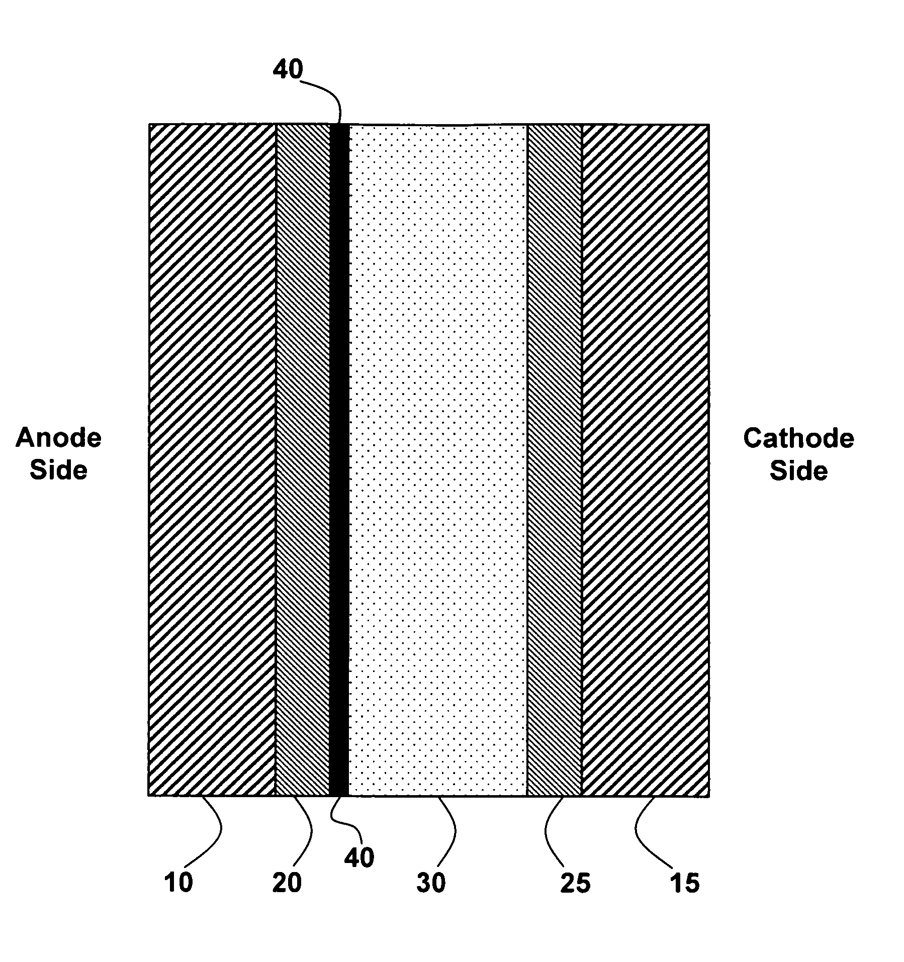
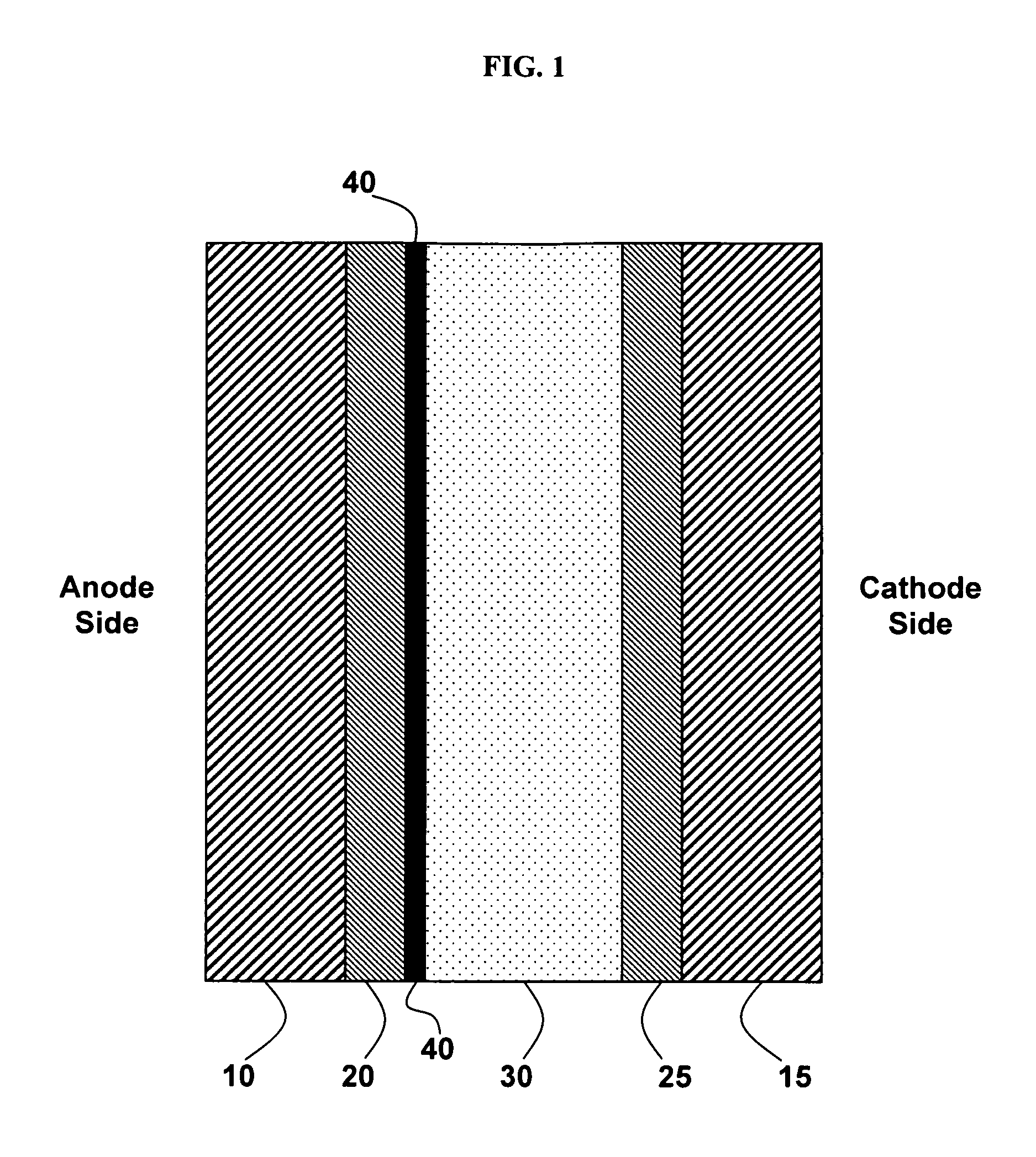
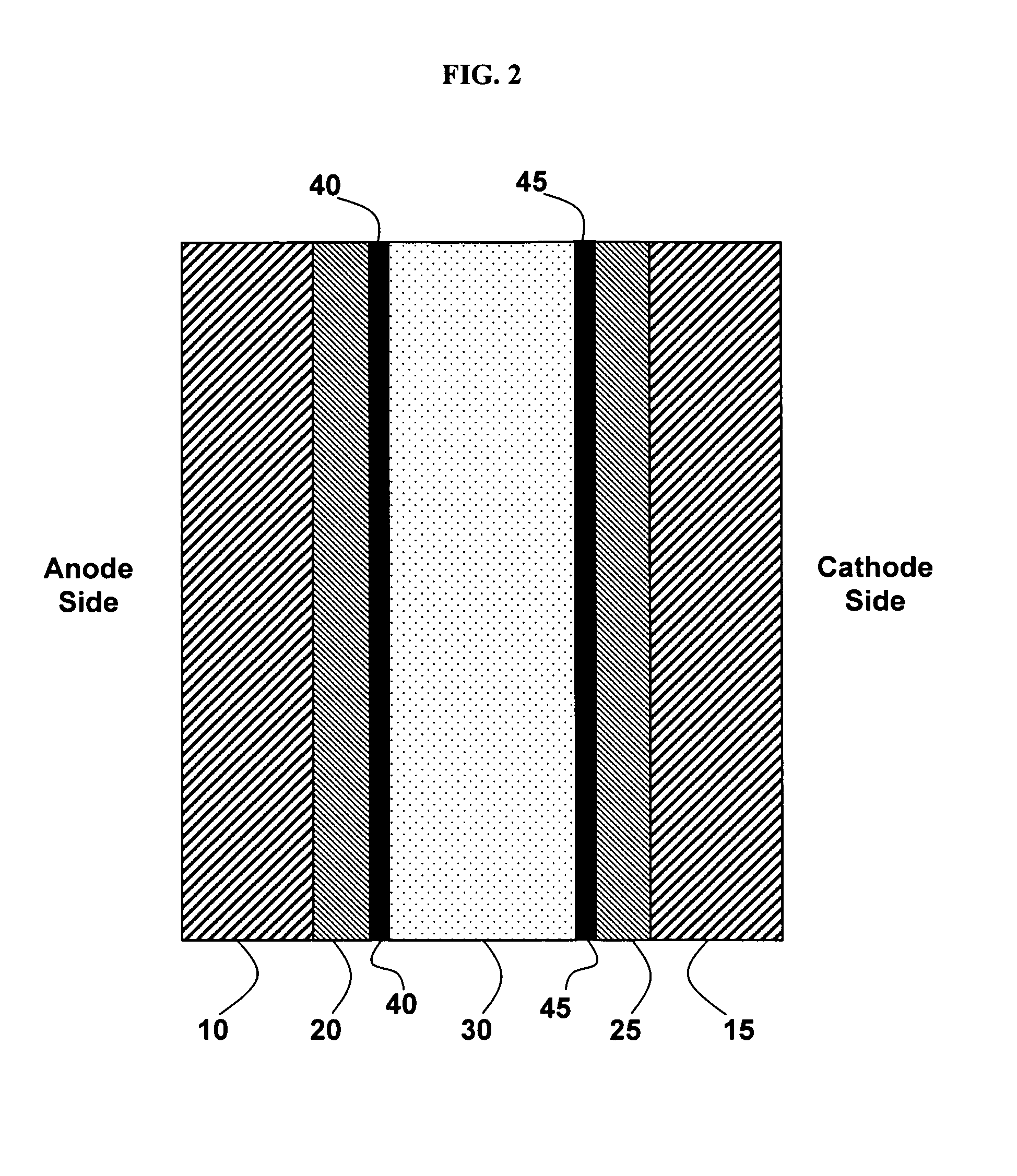
[0087]This Example 1 discloses the formation of a tungsten oxide-coated fuel-cell membrane.
[0088]Nafion is prepared by receiving 0.180-mm-thick Nafion from Alfa Aesar (Ward Hill, Mass., U.S.), cutting the Nafion into 4″×4″ squares, boiling the Nafion in deionized water for one hour and then boiling the Nafion in 0.1 M HCl for one hour. Then the Nafion squares are removed from the HCl solution, washed with deionized water, and stored in a deionized water bath.
[0089]A tungsten oxide sol is prepared by first making a solution of 24 g 50 wt % H2O2 and 28 g deionized H2O. The solution is stirred rapidly and 8 g of W powder is slowly added over two hours. The reaction between hydrogen peroxide and tungsten is very exothermic. When the solution begins to boil, it is placed in a room-temperature water bath while being stirred.
[0090]The hydrogen peroxide in the tungsten oxide sol is then neutralized by placing a platinum mesh in the solution and putting the solution in an 80° C. oven for 25 ...
example 2
[0094]This Example 2 describes the results of testing a tungsten oxide-coated fuel-cell membrane fabricated according to Example 1.
[0095]The membrane is tested in a direct methanol fuel cell. DMFC membranes are made using electrodes produced by E-TEK (BASF Fuel Cell GmbH, Frankfurt, Germany), unsupported High Power (HP) Pt:Ru (1:1) alloy black 5.0 mg / cm2 loading for the anode and unsupported HP Pt black 5.0 mg / cm2 loading for the cathode. The tungsten oxide-coated Nafion is hydrated for about 10 minutes in deionized water. Then a 1″×1″ anode is placed on the tungsten oxide-coated side of the Nafion and a 1″×1″ cathode is placed on the opposite side. The DMFC membrane stack is pressed together in a 150° C. heated press for 5 minutes between 31 mil shims (intended to limit the maximum compression during pressing). Then the heated press is water-cooled to 50° C. and the pressure is released.
[0096]A fuel cell membrane electrode assembly is assembled under 15 inch-pounds of pressure in a...
example 3
[0097]The fuel cell membrane electrode assembly provided according to Example 2 is tested in this Example 3. Fuel cell performance is evaluated using a Solartron (Farnborough, Hampshire, U.K.) SI 1287 Electrochemical Interface.
[0098]Methanol flow is provided at 1 mL / min and humidified oxygen flow is provided at 164-215 mL / min. The results of the electrochemical testing demonstrate the performance benefit provided by the tungsten oxide coating. FIG. 3, which plots the fuel-cell open circuit voltage (OCV) versus methanol concentration, shows the difference in OCV operating with and without the tungsten oxide coating. The OCV represents the fuel cell output voltage when no current load is connected to the fuel cell apparatus.
[0099]The additional tungsten oxide inorganic layer provides a large advantage over the control (uncoated Nafion), particularly at elevated temperatures and high methanol concentrations. The higher OCV indicates a reduction in fuel crossover achieved with the modif...
PUM
 Abstract
Description
Claims
Application Information