
Optical compensation film, polarizing plate and liquid crystal display

a technology of optical compensation film and liquid crystal display, which is applied in the direction of polarizing elements, lighting and heating apparatuses, instruments, etc., can solve the problems of insufficient pasting ability, inability to provide function, and inability to stabilize wavelength dispersion characteristics, so as to achieve retardation and wavelength dispersion characteristics, improve visibility, and improve the effect of front contras

Active Publication Date: 2014-06-17
KONICA MINOLTA OPTO
View PDF10 Cites 2 Cited by
  • Summary
  • Abstract
  • Description
  • Claims
  • Application Information

AI Technical Summary

Benefits of technology

The present invention provides an optical compensation film that can improve the visibility of a liquid crystal display device by reducing light leakage, color tone fluctuation, and front contrast. The film satisfies both a retardation and wavelength dispersion characteristic. This optical compensation film is useful in a polarizing plate and liquid crystal display device.

Problems solved by technology

However, even if such a technology is used, as an optical compensation film which serves as a polarizing plate protective film, it has an insufficient pasting ability with polyvinyl alcohol being a polarization film, and a polarizing plate protective film consisting of a cellulose ester film has been recognized to be an indispensable optical film in a liquid crystal display even now.
Basically, since a cellulose ester film has the circumstances where it has been used as a polarizing plate protective film due to its low birefringence characteristic, it may be not easy to provide the function.
In order to acquire a desired retardation value, a technique to add a compound having a retardation increasing effect to a cellulose ester film- and to further stretch the film is proposed (Patent Documents 1, 2, 3, 4, 5), but there are problems that the wavelength dispersion characteristic does no stabilize over time and the permeability of the film is deteriorated by the stretching.
If the wavelength dispersion characteristic is insufficient, phenomena such as light leakage from a polarizing plate (especially light leakage with an elapse of time), color tone fluctuation of an image on a liquid crystal display and front contrast deterioration occur.

Method used


Image

  • Optical compensation film, polarizing plate and liquid crystal display
  • Optical compensation film, polarizing plate and liquid crystal display
  • Optical compensation film, polarizing plate and liquid crystal display

Examples


example 1

Example According to the First Embodiment

Production of Cellulose Ester Film 101

[0384]

Particulate (Aerosil 972 V 11 parts by weightManufactured by Japan Aerosil)Ethanol89 parts by weight

[0385]The substances listed above were agitated and mixed by a dissolver for 50 minutes and then dispersed by the use of Manton Gaulin.

[0386]The particulate dispersion liquid 1 was slowly added into a solution tank storing methylene chloride, while being agitated sufficiently. Furthermore, the solution was dispersed by an at-righter so that the particle size of secondary particles became a predetermined size. The resultant solution was filtered by the use of Fine Met NF manufactured by Nippon Seisen Co., Ltd., whereby particle addition liquid 1 was prepared.

[0387]

Methylene chloride99 parts by weightParticulate dispersion liquid 1 5 parts by weight

[0388]A main dope liquid of the following composition was prepared. First, methylene chloride and ethanol were added to a pressure solution tank. Cellulose e...

example 2

Preparation of Polarizing Plate

[0435]A polyvinyl alcohol film having a thickness of 120 μm was uniaxially stretched (temperature 110° C., stretching ratio: 5 times).

[0436]The film was immersed in an aqueous solution of 0.075 g iodine, 5 g potassium iodide, and 100 g water for 60 seconds, and then immersed in a 68° C. aqueous solution of 6 g potassium iodide, 7.5 g boric acid and 100 g water. The film was washed and dried to obtain a polarizing film.

[0437]Next, the polarizing film and the cellulose ester films 101 to 207 of the present invention were pasted onto the front side and a Konica Minolta TAC KC4UY (cellulose ester film manufactured by Konica Minolta Opt. Corp. was pasted on the back side in accordance with the following steps 1 to 5, whereby polarizing plates were prepared.

[0438]Step 1: The cellulose ester films were immersed for 90 seconds in 2 mol / L of sodium hydroxide solution at 60° C. and then washed and dried, whereby the cellulose ester films whose side to be pasted ...

example 3

Example According to the Second Embodiment

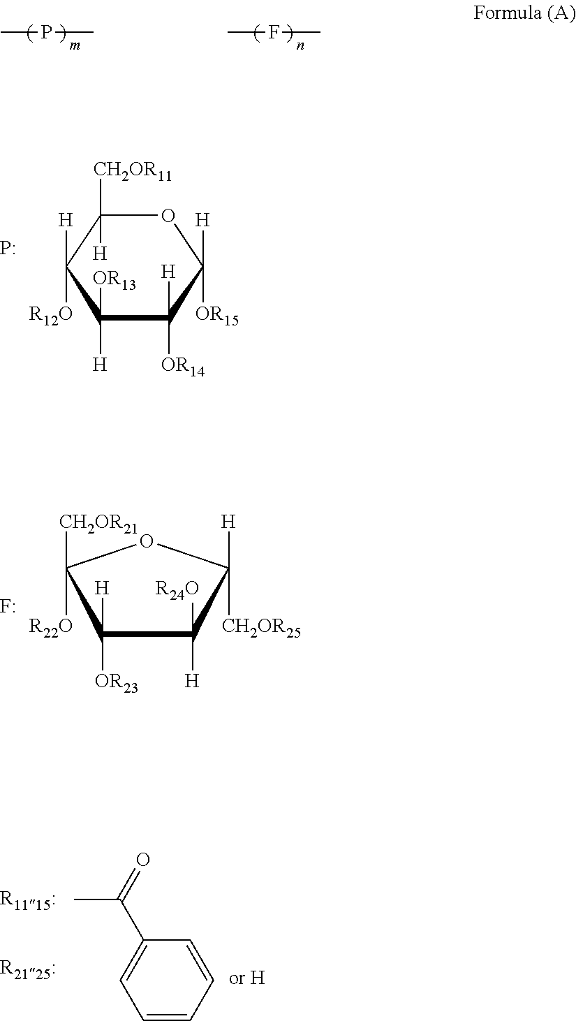
[0451]The cellulose ester, the (meth)acrylic polymer, the compound (sugar ester compound) having a furanose structure or pyranose structure, the plasticizer, and the ultraviolet absorber which were used in Example 3 are shown in Table 5.

[0452]

TABLE 5CelluloseAcyl groupTotal acyl groupestersubstitution degreesubstitution degreeAAcetyl group: 1.92.7Propionyl group: 0.8BAcetyl group: 1.62.5Propionyl group: 0.9CAcetyl group: 1.12.0Propionyl group: 0.9DAcetyl group: 1.22.3Propionyl group: 1.1EAcetyl group: 2.42.4FAcetyl group: 1.32.5Propionyl group: 1.2(Meth)acrylicMolecularpolymerMain compositionweightRatioAPolymethyl acrylate1000100Bmethyl methacrylate / 400090 / 10hydroxyethyl methacrylateSugar estercompoundACompound 3BCompound 5CMixing compounds 6 and 7 withratio of 1:1 by weightDCompound 8PlasticizerATriphenyl phosphateBEthylphthalyl ethylglycolateCTrimethylolpropan tribenzoateUltravioletabsorbentATinuvin 326 (Ciba Specialty Chemicals)BTinuvin 1...


PUM

PropertyMeasurementUnit
thicknessaaaaaaaaaa
thicknessaaaaaaaaaa
thicknessaaaaaaaaaa

Abstract

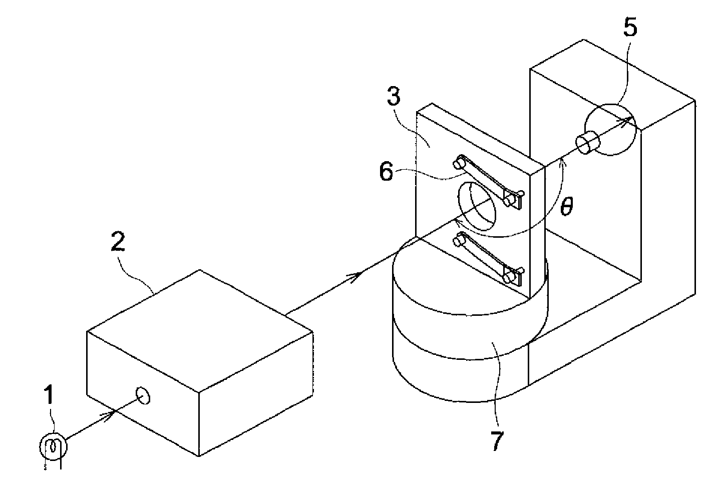
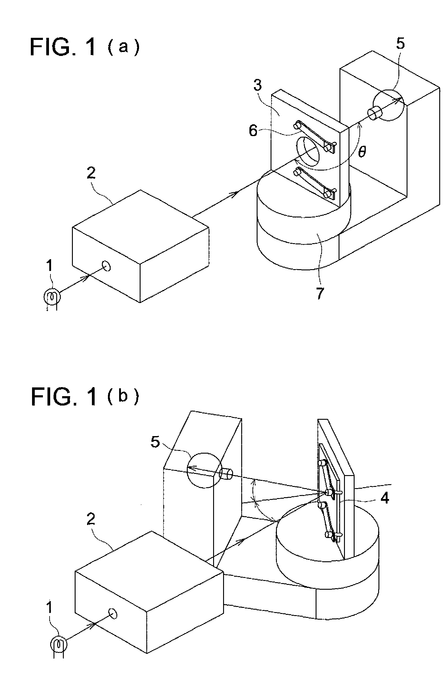
An optical compensation film and a liquid crystal display characterized in that in a scattered-light intensity measurement for a film with an incident light with 90° in a scattered light profile of a goniophotometer, in the case of measuring so as to detect a scattered light intensity at the position of 130° from a light source, a difference in scattered light intensity between the case where a film slow axis is installed horizontally on a sample stand and the case where the film slow axis is installed vertically is 0.05 or less.

Description

TECHNICAL FIELD[0001]The present invention relates to an optical compensation film used for a liquid crystal display, in particular, relates in detail to an optical compensation film which is excellent in visibility (light leakage, color tone unevenness, front contrast), and compatible to both retardation and wavelength dispersion characteristic, and relates to a polarizing plate and a liquid crystal display device employing the optical compensation film.TECHNICAL BACKGROUND[0002]A cellulose ester film, a polycarbonate film, a poly cyclic olefin film, and so on are widely used as an optical film for liquid crystal displays.[0003]It is required for an optical film that its transparency should be optically high and also its birefringence should be low. Especially, in recent years, the size of a liquid crystal display becomes lager and the luminance becomes higher and higher. In connection with these, an improvement in front contrast is demanded more severely than ever before.[0004]Sin...

Claims


Application Information

Patent Timeline
Patent Type & Authority Patents(United States)
IPC IPC(8): C09K19/00
CPCG02F2001/133637G02F1/133634G02B5/3083G02F1/133637B32B27/30C08J5/18G02B5/30G02F1/13363C09K2323/00C09K2323/03C09K2323/035
Inventor SERA, TAKASHITAKAGI, TAKAHIRO
Owner KONICA MINOLTA OPTO
Learn More