VCSEL pumped fiber optic gain systems

a fiber optic gain and fiber optic technology, applied in the direction of optical elements, semiconductor lasers, instruments, etc., can solve the problems of misalignment between the pump wavelength and the absorption line of the doping ions, complex arrangement, and design of the v-groove, so as to enhance the input optical pump power, boost the laser output power, and increase the output power

Active Publication Date: 2014-09-02
PRINCETON OPTRONICS
View PDF20 Cites 28 Cited by
  • Summary
  • Abstract
  • Description
  • Claims
  • Application Information

AI Technical Summary

Benefits of technology

[0021]In a different embodiment, a fiber laser may be cascaded with a fiber amplifier in order to boost laser output power. The combination may provide a desirable level of laser power without increasing the pump input power to operate the fiber laser. In an alternative configuration of fiber laser and amplifier, output from several pump modules may be combined to enhance input optical pump power to a doped fiber gain medium in order to obtain higher output power. In yet another embodiment, pump modules may be applied to a gain medium from one end or from both ends.

Problems solved by technology

However this is a very complex arrangement where multiple single mode Er doped fiber amplifiers using Raman pumps, are used as pump source.
However, one disadvantage of this configuration is that the V-groove is designed integral to the cladding layer and works well for a specific pump wavelength.
While pumps using edge emitter lasers are useful for pumping doped core of fiber lasers and amplifiers, edge emitter lasers have a relatively broad linewidth and all the light emitted by the pump laser does not contribute towards exciting the doping ions which absorb only in a narrow wavelength band.
Furthermore, edge emitter laser wavelength varies considerably with operating temperature resulting in misalignment in the pump wavelength and the absorption lines of the doping ions.
One major disadvantage of this approach is that for high optical power application, the wire bonding is prone to failure, thereby imposing a practical limitation on output power that can be obtained from such pumps.

Method used


Image

  • VCSEL pumped fiber optic gain systems
  • VCSEL pumped fiber optic gain systems
  • VCSEL pumped fiber optic gain systems

Examples


Embodiment Construction

[0039]A broad framework of the principles will be presented by describing various aspects of this invention in exemplary embodiments shown in different drawing figures. For clarity and ease of description, each embodiment includes only a few aspects. However, different aspects from different embodiments may be combined or used separately, to put the invention to practice. Many different combinations and sub-combinations of the representative embodiments within the broad framework of this invention, that may be apparent to those skilled in the art but not explicitly shown or described, should not be construed as precluded.

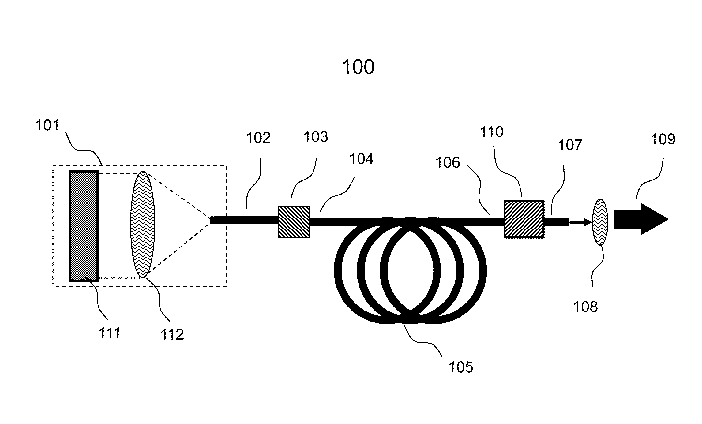
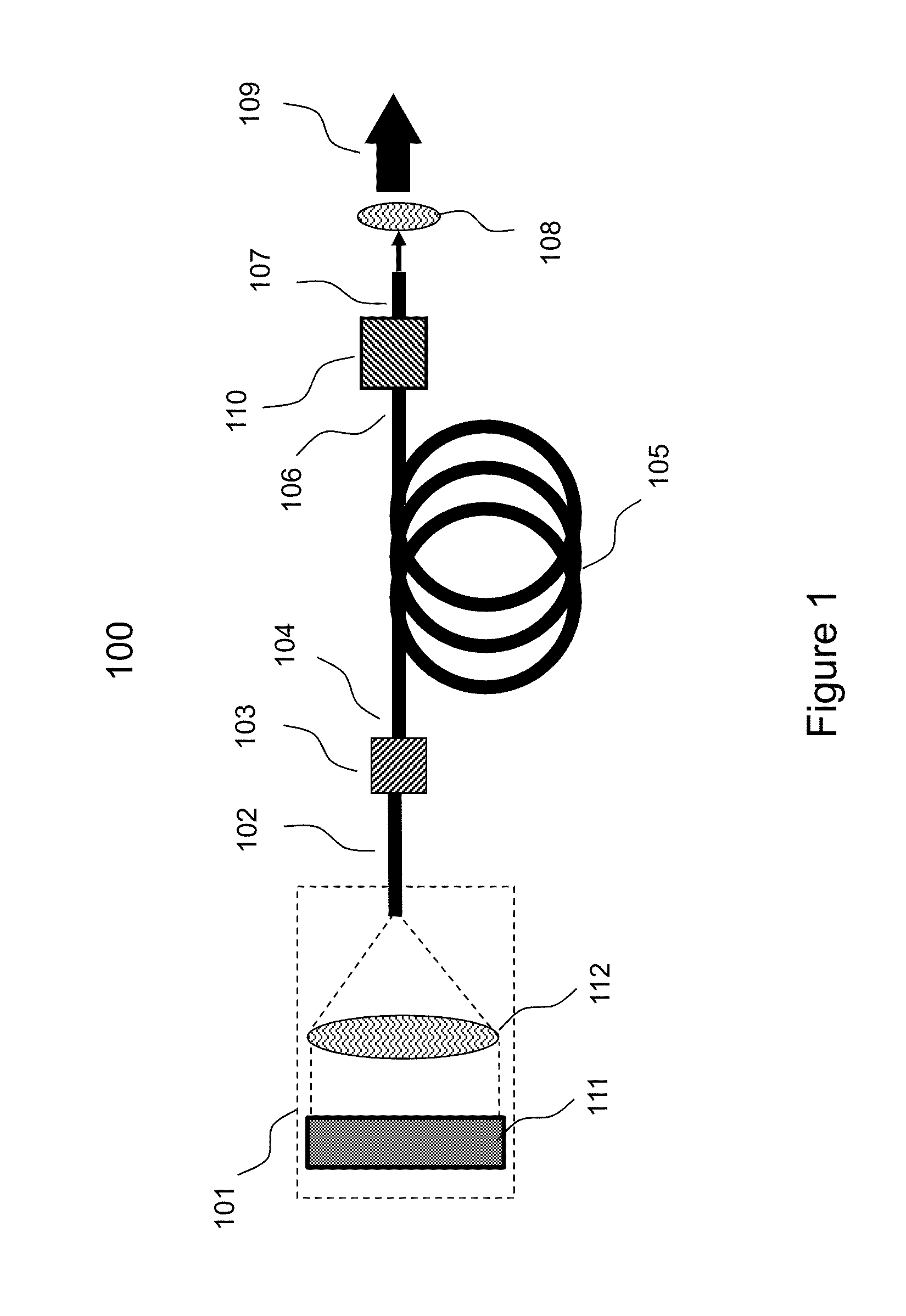
[0040]FIG. 1 shows an exemplary fiber optic gain system 100 to explain different aspects of the invention that may be configured to practice the invention in different modes. The fiber optic system is represented in terms of basic building blocks to illustrate the broad principles and should not be construed as limiting. Details of each block will be elaborated late...


PUM


Abstract

Optical pump modules comprising VCSEL and VCSEL array devices provide high optical power for configuring fiber optic gain systems such as fiber laser and fiber amplifier particularly suited for high power operation. Pump modules may be constructed using two reflector or three reflector VCSEL devices optionally integrated with microlens arrays and other optical components, to couple high power pump beams to a fiber output port. The pump module having a fiber output port is particularly suited to couple light to an inner cladding of a double-clad fiber, often used to configure high power fiber laser and fiber amplifier. The pump modules may be operated in CW, QCW and pulse modes to configure fiber lasers and amplifiers using single end, dual end, and regenerative optical pumping modes. Multiple-pumps may be combined to increase pump power in a modular fashion without significant distortion to signal, particularly for short pulse operation.

Description

BACKGROUND OF THE INVENTION[0001]1. Field of Invention[0002]The present invention relates to fiber optic gain systems and in particular to fiber optic lasers and amplifiers including Vertical Cavity Surface Emitting Laser (VCSEL) optical pumps.[0003]2. Background Art[0004]Fiber optic lasers and amplifiers (hereinafter referred as fiber lasers and fiber amplifiers, respectively) are well known in the art for their excellent conversion efficiency, beam quality, small volume, light weight, and low cost. Primarily, fiber lasers and fiber amplifiers have an optical gain medium, typically comprising an optical fiber doped with optically active ions in a core region surrounded by a cladding region. For example, the core may be doped with selective rare-earth ions which upon absorbing optical power from an intense light source such as a high power optical pump, are excited to a higher energy state and when the excited ions return to their ground state they provide optical gain or amplificat...

Claims


Application Information

Patent Timeline
Patent Type & Authority Patents(United States)
IPC IPC(8): H01S3/30H01S5/00H01S3/08H01S3/067
CPCH01S3/06754H01S5/423H01S5/183H01S5/4012H01S5/02284H01S3/067H01S3/1068H01S3/0941H01S3/091H01S3/094053H01S5/50H01S3/10H01S3/0675H01S3/094007H01S3/09415H01S3/235H01S5/005H01S5/02208H01S5/026H01S5/141H01S5/18305G02B6/4206H01S5/02251H01S3/1123
Inventor SEURIN, JEAN-FRANCOISWANG, QINGWATKINS, LAURENCEGHOSH, CHUNI LAL
Owner PRINCETON OPTRONICS
Why Eureka
Try Eureka