Melt containment member

Active Publication Date: 2014-09-09
IOWA STATE UNIV RES FOUND
View PDF7 Cites 1 Cited by
  • Summary
  • Abstract
  • Description
  • Claims
  • Application Information

AI Technical Summary

Benefits of technology

[0010]A tubular melt containment member can comprise an elongated melt supply tube or pour tube in certain illustrative embodiments of the invention. For example, the pour tube can be used for the atomization of highly reactive metals, specifically titanium and titanium alloys, wherein use of a highly stable and less reactive pour tube will result in production of metallic powders that will contain significantly less interstitial impurities (e.g., oxygen) which, when consolida

Problems solved by technology

Highly reactive metals (e.g., titanium and zirconium) are extremely difficult to handle in their molten state due to their extreme corrosive nature.
However, due to the nature of the water-cooled copper, limited geometrical variations are possible.
However, Y2O3 does have limitations with respect to its protection for extended times or increased melt superheat (i.e., temperature above the melting point).
1972), increased time or superheat will cause dissolution of the Y2O3 into the molten titan

Method used


Image

  • Melt containment member
  • Melt containment member
  • Melt containment member

Examples


Example

Example #1

[0037]High purity yttria powder with a size −6 torr and heated to 1800° C. for 16 hours to transform then to sub-stoichiometric yttria.

[0038]One of the crucibles was then placed in a furnace at 1200° C. for approximately 10 minutes to revert it back to stoichiometric yttria.

[0039]Small samples of high purity titanium were placed into the yttria crucibles and were placed inside a tantalum can sheathed with pyrrolitic graphite. The can was placed in a high vacuum to 1×10⁻⁶ torr before backfilling to a sub-atmospheric pressure of ultra high purity argon. The furnace was ramped up to 1800° C. (i.e., approximately 140° C. above the melting temperature of titanium) and held for 15 minutes before cooling. The titanium melted in the yttria crucibles and re-solidified upon cooling.

[0040]Examination was conducted by cross-sectioning the stoichiometric and sub-stoichiometric crucibles with a diamond saw. Upon sectioning, the re-solidified titanium in the sub-stoichiometric yttria cru...

Example

Example #2

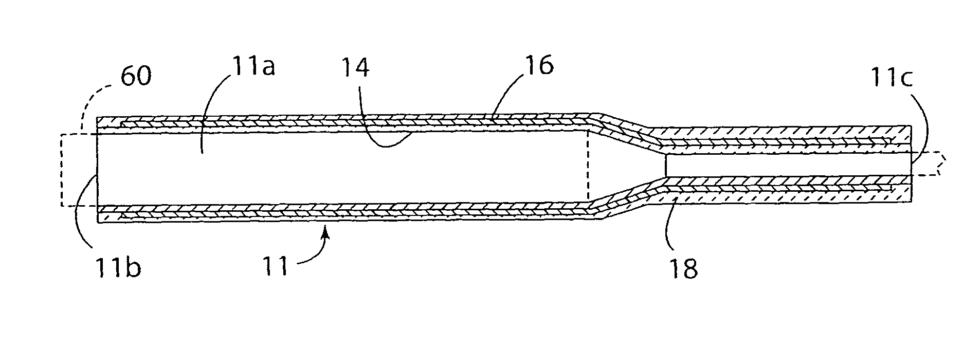
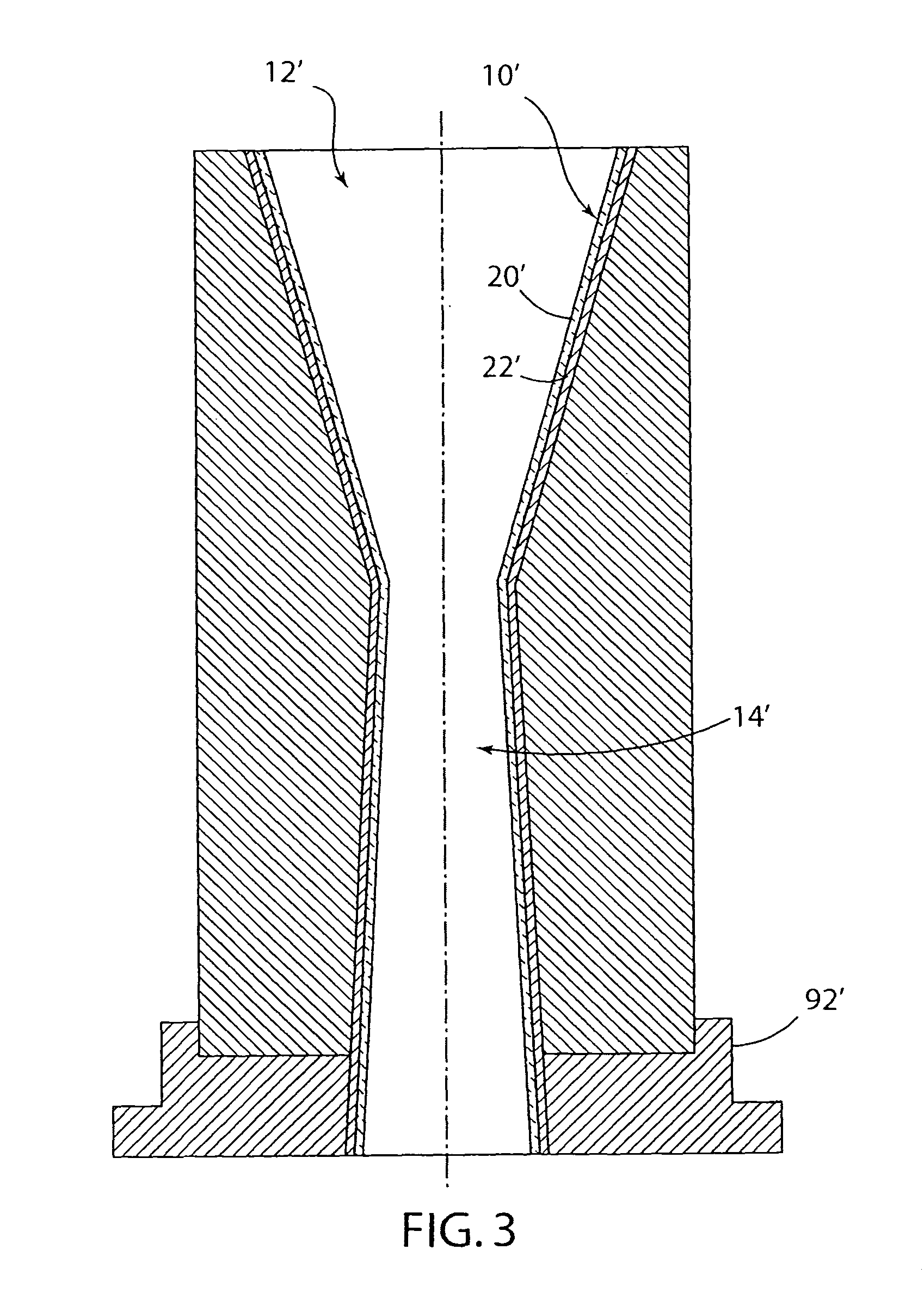
[0041]A pour tube fabricated with a stoichiometric yttria melt contacting layer was fabricated as described by U.S. Pat. No. 6,358,466. The pour tube was installed in a cold wall crucible atomization system located at the University of Birmingham in the United Kingdom. Molten Ti-6Al-4V (wt %) was melted in the cold wall crucible. An electromagnetic field around the pour tube was generated with an induction power supply and was tapped by the thermal radiation generated by the heat-generating layer and was directed to the interior cavity of the pour tube. The molten titanium alloy flowed through the pour tube, free fell for approximately two seconds, and was subsequently contained in a mild steel can lined with boron nitride. The molten Ti-6Al-4V had a melt exit temperature of 1675° C. and was flowed for a duration of 45 seconds.

[0042]Post-experiment analysis of the pour tube was conducted by cross-sectioning the pour tube perpendicular to the melt flow direction. The cross-...


PUM

PropertyMeasurementUnit
Metallic bondaaaaaaaaaa
Melt temperatureaaaaaaaaaa

Abstract

A tubular melt containment member for transient containment of molten metals and alloys, especially reactive metals and alloys, includes a melt-contacting layer or region that comprises an oxygen-deficient rare earth oxide material that is less reactive as compared to the counterpart stoichiometric rare earth oxide. The oxygen-deficient (sub-stoichiometric) rare earth oxide can comprise oxygen-deficient yttria represented by Y2O3-x wherein x is from 0.01 to 0.1. Use of the oxygen-deficient rare earth oxide as the melt-contacting layer or region material reduces reaction with the melt for a given melt temperature and melt contact time.

Description

[0001]This application is a division of U.S. application Ser. No. 12 / 928,702 filed Dec. 16, 2010, now abandoned which claims priority and benefits of U.S. provisional application Ser. No. 61 / 284,514 filed Dec. 21, 2009, the disclosures of which are incorporated herein by reference.CONTRACTUAL ORIGIN OF THE INVENTION[0002]This invention was made with government support under Grant No. DE-AC02-07CH11358 awarded by the U.S. Department of Energy. The Government has certain rights in the invention.FIELD OF THE INVENTION[0003]The present invention relates to a melt containment member for transient containment of molten metals or alloys, especially highly reactive metals and alloys.BACKGROUND OF THE INVENTION[0004]When considering traditional refractory materials for primary metallurgical processing of most metals, the oxides of aluminum, Al2O3, silicon, SiO2, and zirconium, ZrO2 are exclusively used. They are embodied in either transient melt containment members, such as pour tubes, or as...

Claims


Application Information

Patent Timeline
IPC IPC(8): B29C67/00B22D11/00B22C3/00B22D25/02B22D25/00
CPCB22D11/00B22D25/02B22D41/54B22D11/059B29C67/0014B22D25/00
Inventor RIEKEN, JOEL R.HEIDLOFF, ANDREW J.
Owner IOWA STATE UNIV RES FOUND
Why Eureka
Try Eureka