Process for selective removal of a product from a gaseous system

a gaseous system and product technology, applied in the direction of specific gas purification/separation, chemical production, electrodialysis, etc., can solve the problems of poor efficiency, less selective, poor efficiency of the membrane-based system, etc., to improve the conversion rate, improve the efficiency, and improve the conversion rate

Active Publication Date: 2014-10-28
CASALE SA
View PDF21 Cites 1 Cited by
  • Summary
  • Abstract
  • Description
  • Claims
  • Application Information

AI Technical Summary

Benefits of technology

[0042]The main advantage of the invention is the better conversion of the reagents, due to the ability to increase the rate of the conversion by removing products form the flowing system. Generally speaking, a synthesis section of a chemical product, is made more efficient and less energy consuming. Another related advantage is the lower consumption for the feed of the reagents: this advantage is felt e.g. in the field of synthesis of methanol and in the field of synthesis of ammonia, where the power for compression of the make-up gas containing the reagents is significant. The need to consume power for re-circulating the gaseous products is also reduced. Another positive effect of the invention is that the chemical reaction (if exothermic) delivers more heat, due to the better yield of conversion. When the heat removal produces a useful effect, for example heat is removed producing hot steam which is used in the process, a further advantage is produced.
[0043]The process is now elucidated in a greater detail.
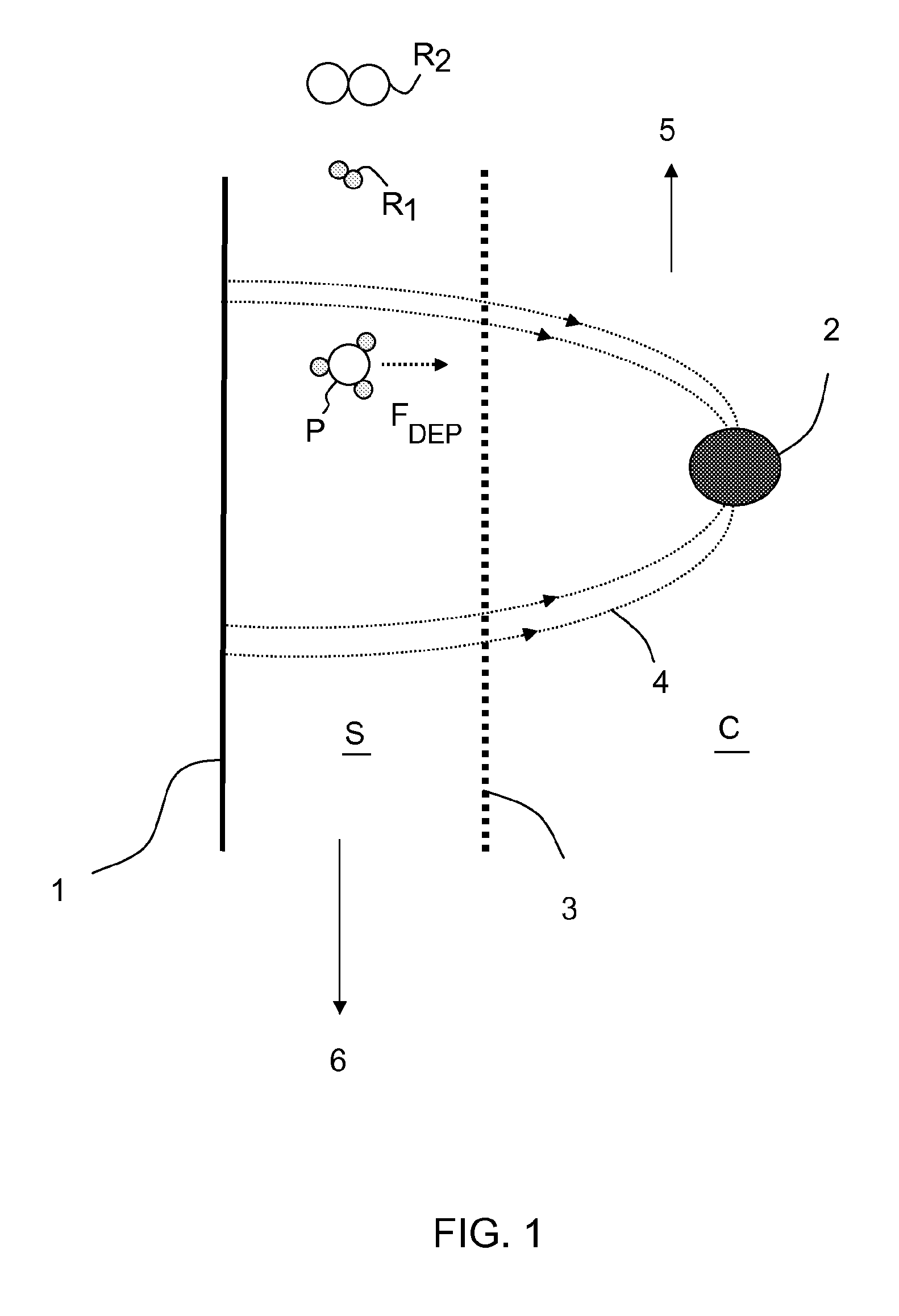
[0044]The spatially non-uniform electric field generates dielectrophoretic force FDEP on the polarised particles. Said force points to the region where the electric field is stronger. This force can be defined by the following formula (I):
[0045]The formula (I) can be further developed considering that the induced dipole moment depends on the volume of the particle and effective polarizability, namely:
[0046]Taking into account the formula (II), the formula (I) is rewritten as:
[0052]In a preferred embodiment said membrane is a microporous membranes with a pore diameter<2 nm (2 10−9 m). Preferably the electric field dimensions are several times smaller than the dimensions of the membrane pores allowing an efficient electric field development.

Problems solved by technology

This means that a membrane-based system has a poor efficiency (i.e. is less selective) when products and reagents have a comparable molecular size, and is even less efficient when a product has a molecular size smaller than one or more of reagents.
For example, the size of the ammonia (NH3) molecule is 2.90 Angstrom (A) which is between the size of molecular hydrogen (2.83 A) and size of molecular nitrogen (3.78 A) and, thus, a selective removal of NH3 with conventional membranes is not efficient, because a significant amount of hydrogen would escape from the system, together with ammonia.
The same happens e.g. in the synthesis of methanol since the size of the molecule CH3OH is comparable with that of carbon oxide and carbon dioxide and, then, membrane-based selective removal is not efficient.
It has to be noted that a conventional membrane-based system would not accomplish any separation in absence of at least one of the above mentioned driving forces across the membrane.
As stated above, drawbacks of the known membrane-based separation technique are: poor selection between gas molecules having the same size or a similar size; need of a driving force in terms of a significant pressure difference across the membrane, or need of ionization in order to make the molecules sensitive to an electric field.
Aiming to recover at least part of said reagents, a relevant fraction of the output stream is usually re-circulated to the reactor; the power demand for compressing back the output stream at the pressure of the chemical reaction, however, affects the overall efficiency of the process.

Method used


Image

  • Process for selective removal of a product from a gaseous system
  • Process for selective removal of a product from a gaseous system
  • Process for selective removal of a product from a gaseous system

Examples


example

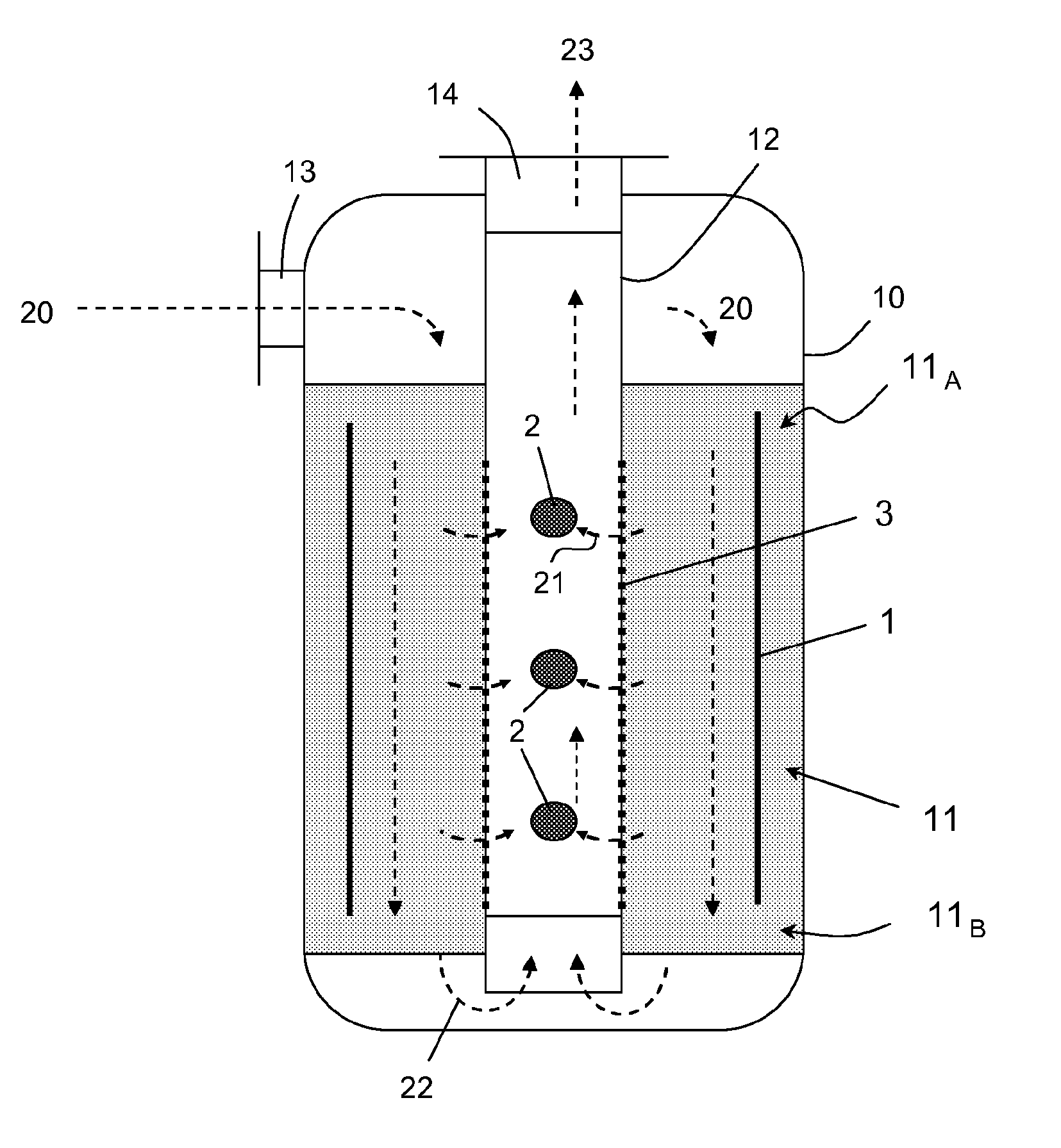
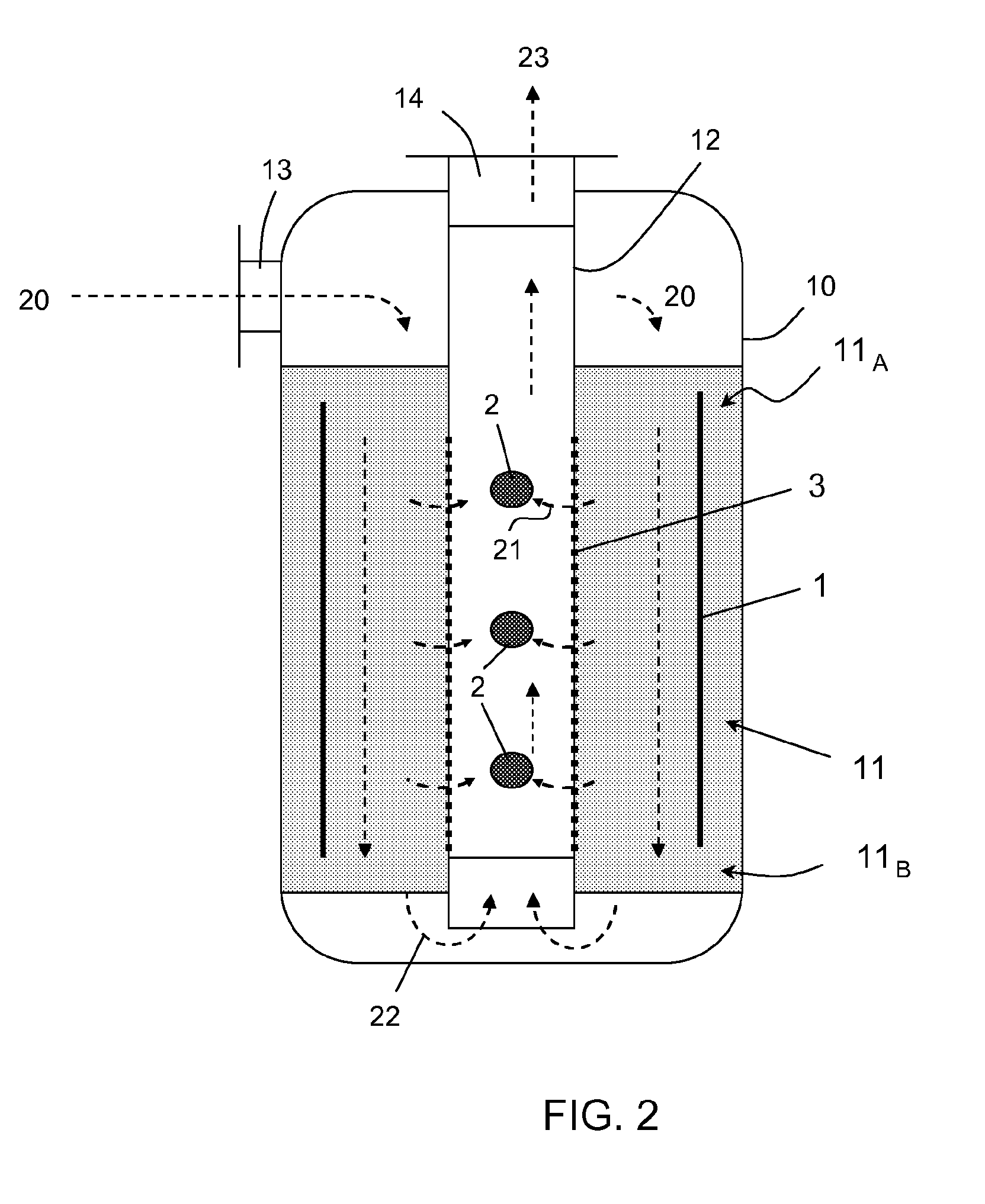
[0083]An example of application of the invention to a three-bed quenched converter is presented.

[0084]FIG. 4 discloses a bottle shape converter according to a quench-interchanger design. This converter is known e.g. from U.S. Pat. No. 4,735,780 and is not described in detail. FIG. 5 discloses a flow diagram of the converter. Basically, the converter comprises: a vessel 130, a catalytic cartridge 131, said cartridge containing three catalytic bed 132, 133 and 134; a shell-and-tube top preheater 135, an inter-bed heat exchanger 136 traversed by the gas flow between the second bed 133 and the third bed 134. The inter-bed exchanger 136 is a tube bundle heat exchanger.

[0085]A feed gas stream 101 enters the converter through a bottom nozzle 137 of the vessel and flows upward flushing the vessel in an annular space 138 between the vessel 130 and the cartridge 131. Having reached the top of the converter, the feed gas enters the shell side of the top preheater 135 where it is preheated by c...


PUM

PropertyMeasurementUnit
voltageaaaaaaaaaa
electric fieldaaaaaaaaaa
sizeaaaaaaaaaa

Abstract

A process for selective removal of a gaseous product (P) from a gaseous system comprising said product and other components (R1, R2), wherein the gaseous system is admitted to a first environment, which is separated from a second environment by a boundary wall, and a permeation membrane (3, 300) forms at least part of said boundary wall; a spatially non-uniform electric field (4) is generated between a first electrode or first plurality of electrodes (1, 301) located in the first environment and a second electrode or second plurality of electrodes (2, 302) located in the second environment, so that field lines of said non-uniform electric field cross said membrane, and a dielectrophoretic force generated on particles of said gaseous component (P) is at least part of a driving force of the permeation through said membrane, an amount of said product (P) being selectively removed from the first environment and collected in the second environment.

Description

[0001]This application is a national phase of PCT / EP2011 / 059655, filed Jun. 10, 2011, and claims priority to EP 10168010.6, filed Jun. 30, 2010, the entire contents of both of which are hereby incorporated by reference.FIELD OF THE INVENTION[0002]The invention relates to methods for carrying out chemical reactions and related reactors. The invention relates in particular to selective removal of a gaseous component of a gaseous system. More in detail the invention allows selective removal of reaction products from a gaseous system comprising reagents and products. The invention is applicable to several processes including: synthesis of ammonia, methanol, DME, nitric acid, sulphuric acid, which are cited as non limitative examples. The invention discloses also a reactor adapted to carry out said process of selective removal.PRIOR ART[0003]Removal of reaction products is a known measure to increase the yield of a chemical reaction. By removing products form the evolving system, the rat...

Claims


Application Information

Patent Timeline
Patent Type & Authority Patents(United States)
IPC IPC(8): B01J8/00B01D53/32B01J8/04B01J8/02C01C1/04
CPCC01B2210/0012B01D53/32C01C1/0458B01J8/009B01D53/323B01J8/0415C01B2210/001B01D2313/42C01B2210/0053B01J8/0257C01C1/0441C01B2210/0046B01J8/0214Y02P20/52
Inventor PANZA, SERGIO
Owner CASALE SA
Why Eureka
Try Eureka