Power semiconductor device

a technology of semiconductor devices and semiconductor chips, applied in semiconductor devices, semiconductor/solid-state device details, electrical apparatus, etc., can solve the problems of high thermal stress at the joints, inability to maintain the connection between the electrodes formed on the semiconductor chip and the wires, etc., to reduce the likelihood of cracking-destruction, high reliability, and high temperature operation

Inactive Publication Date: 2014-12-02
RESONAC HOLDINGS CORPORATION
View PDF10 Cites 0 Cited by
  • Summary
  • Abstract
  • Description
  • Claims
  • Application Information

AI Technical Summary

Benefits of technology

[0022]According to the present invention, a power semiconductor device can be provided in which the semiconductor device electrode, connection terminal and semiconductor device substrate are conductively connected, and in which the bonding joint reduces the likelihood of cracking-destruction occurring owing to thermal cycle under a temperature environment enabling operation of a wide bandgap semiconductor, namely, of 150° C. or greater. A power semiconductor device of high reliability capable of high-temperature operation can therefore be provided. In addition, a power semiconductor device can be provided that has a bonding joint of high reliability and is low in power loss even when the device is operated at high frequency.

Problems solved by technology

The melting point of Sn / Pb-based solder is about 180° C. When the temperature of the solder rises to near the solder melting point, the solder may soften and make it impossible to maintain the connection between the electrodes formed on the semiconductor chip and the wires.
Further, Patent Document 2 makes known a problem in the power semiconductor module that uses a silicon semiconductor chip and aluminum wires.
Therefore, when the module is heated or cooled, high thermal stress occurs at the joint interface between the wire and the pad (electrode).

Method used


Image

  • Power semiconductor device
  • Power semiconductor device
  • Power semiconductor device

Examples


first embodiment

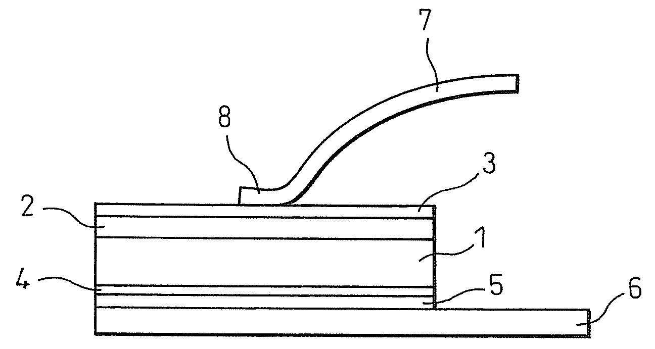
[0041]FIG. 1 is a diagram showing the configuration of the present invention. A silicon carbide substrate (coefficient of linear expansion: 4.2×10⁻⁶ / K) designated by symbol 1 of FIG. 1 is 4H n-type. The silicon carbide substrate 1 is a 5 mm×5 mm square having a thickness of about 200 μm. A silicon carbide homoepitaxial layer designated by symbol 2 of FIG. 1 has a thickness of around 10 μm. A 1 μm thick molybdenum film (coefficient of linear expansion: 4.9×10⁻⁶ / K) 3 is formed on the epitaxial layer 2 by sputtering to form a schottky electrode. Further, symbol 4 of FIG. 1 is a 0.3 μm thick nickel film formed by sputtering. After the nickel film 4 has been formed, heat treatment is performed at 1000° C. for about 2 min to form an ohmic junction on the rear surface of the silicon carbide substrate (semiconductor device substrate) 1. In addition, molybdenum film metal (film) 5 is formed on rear surface of the nickel film 4 by sputtering to a thickness of about 2 μm.

[0042]A bus bar (conne...

second embodiment

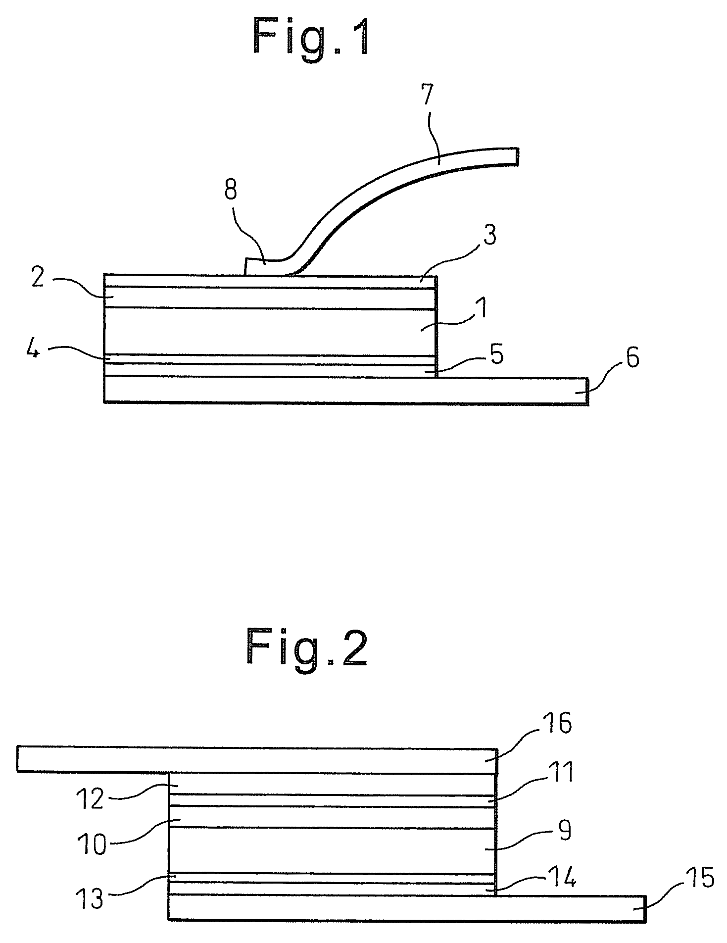
[0047]FIG. 2 is a diagram showing the configuration of the present invention. An n-type GaN substrate (coefficient of thermal expansion: 5.6×10⁻⁶ / K) designated by symbol 9 of FIG. 2 is the size of a 3 mm×3 mm square having a thickness of about 300 μm. The thickness of a GaN homoepitaxial layer (film) designated by symbol 10 of FIG. 2 is about 10 μm. A 0.2 μm thick palladium film (coefficient of linear expansion: 11.8×10⁻⁶ / K) 11 is formed on the epitaxial layer by sputtering to form a schottky electrode. On this is formed by sputtering a 2 μm thick tungsten electrode (coefficient of linear expansion: 4.3×10⁻⁶ / K) 12.

[0048]Further, symbol 13 of FIG. 2 is a titanium and gold multilayer film formed by sputtering to a thickness of 0.3 μm. After formation of the multilayer film 13, heat treatment is performed at 900° C. for about 30 sec to form an ohmic junction on the rear surface of the GaN substrate. In addition, a tungsten metal (film) 14 is formed on the surface of the multilayer film...


PUM


Abstract

Provided is a power semiconductor device comprising a bonding joint that, even under a temperature environment of 150° C. or greater enabling operation of a wide bandgap semiconductor, reduces cracking-destruction occurring owing to thermal cycle while conductively connecting an electrode, connection terminal, and semiconductor device substrate.It is a power semiconductor device capable of operating under a temperature of 150° C. or greater having an electrode laminated on a wide bandgap semiconductor substrate and a connection terminal joined to the electrode for connection to external wiring, which power semiconductor device is characterized in that difference among the three coefficients of linear expansion of the electrode, a core of the connection terminal, and the semiconductor device substrate is 5.2×10⁻⁶ / K at maximum, and that it comprises a joint that directly joins the connection terminal and the electrode.

Description

[0001]This application is a national stage application of International Application No. PCT / JP2011 / 054215, filed Feb. 18, 2011, which claims priority to Japanese Application No. 2010-034284, filed Feb. 19, 2010, the content of which is incorporated by reference in its entirety.TECHNICAL FIELD[0002]This invention relates to a power semiconductor device usable under a high-temperature environment.BACKGROUND ART[0003]Devices used for power conversion include, among others, the diode, transistor, MOSFET and IGBT. These devices are generally formed of silicon semiconductor material. A semiconductor material subjected to various types of processing is diced by the device fabrication process to acquire a semiconductor chip with desired functions. The semiconductor chip is incorporated into a device or module by connecting electrodes formed on the semiconductor chip surface through solder to wires (bonding wires) whose other ends are connected to electrodes for external connection.[0004]The...

Claims


Application Information

Patent Timeline
Patent Type & Authority Patents(United States)
IPC IPC(8): H01L23/00H01L29/15
CPCH01L2924/00015H01L2924/01006H01L24/33H01L2924/01004H01L2924/00014H01L2224/48699H01L2224/48491H01L2924/10254H01L2924/0001H01L2924/01022H01L2224/29111H01L2924/01047H01L2924/13055H01L2924/01079H01L2924/01013H01L2924/10253H01L2924/1033H01L2924/01078H01L2224/45565H01L2924/01031H01L2924/0132H01L2224/45124H01L2924/01028H01L2924/01074H01L2924/20751H01L24/85H01L2224/48599H01L2924/01327H01L2224/85205H01L2924/01082H01L2924/01046H01L2924/10272H01L2924/01042H01L2224/45184H01L2224/45015H01L2924/01033H01L2924/01019H01L2224/45144H01L2924/13091H01L2224/32225H01L2924/014H01L24/48H01L2224/04042H01L2224/45647H01L2224/73265H01L2924/01014H01L2924/13063H01L2924/0105H01L2924/01029H01L2924/01024H01L24/05H01L2224/4847H01L24/83H01L2224/83205H01L2924/12032H01L2924/1301H01L2924/1305H01L2924/13062H01L2924/351H01L24/45H01L2224/05556H01L2924/3512H01L2924/00H01L2224/45147H01L2224/29099H01L2924/00012H01L2924/2075
Inventor HIRANO, HOSEI
Owner RESONAC HOLDINGS CORPORATION
Why Eureka
Try Eureka