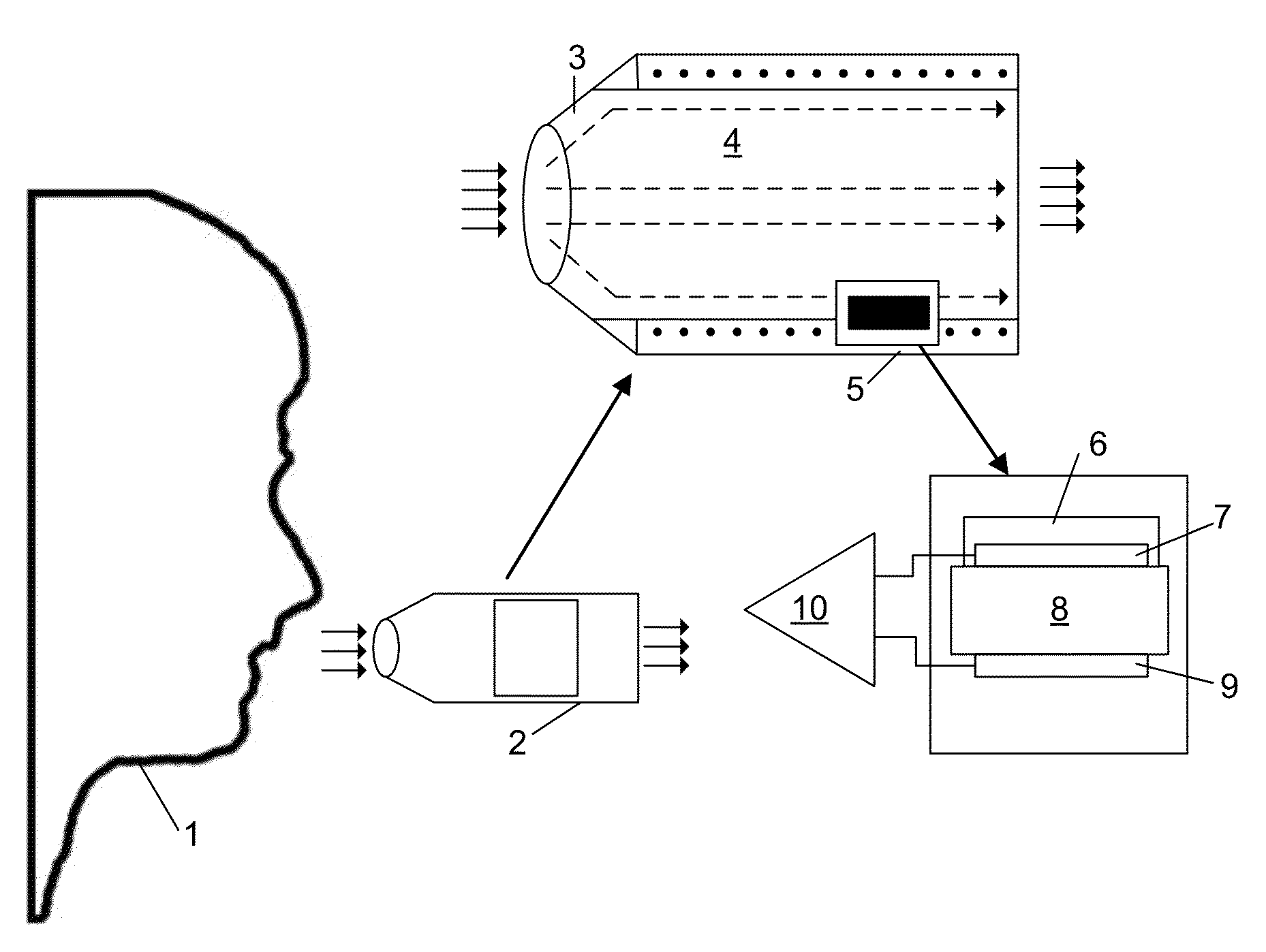
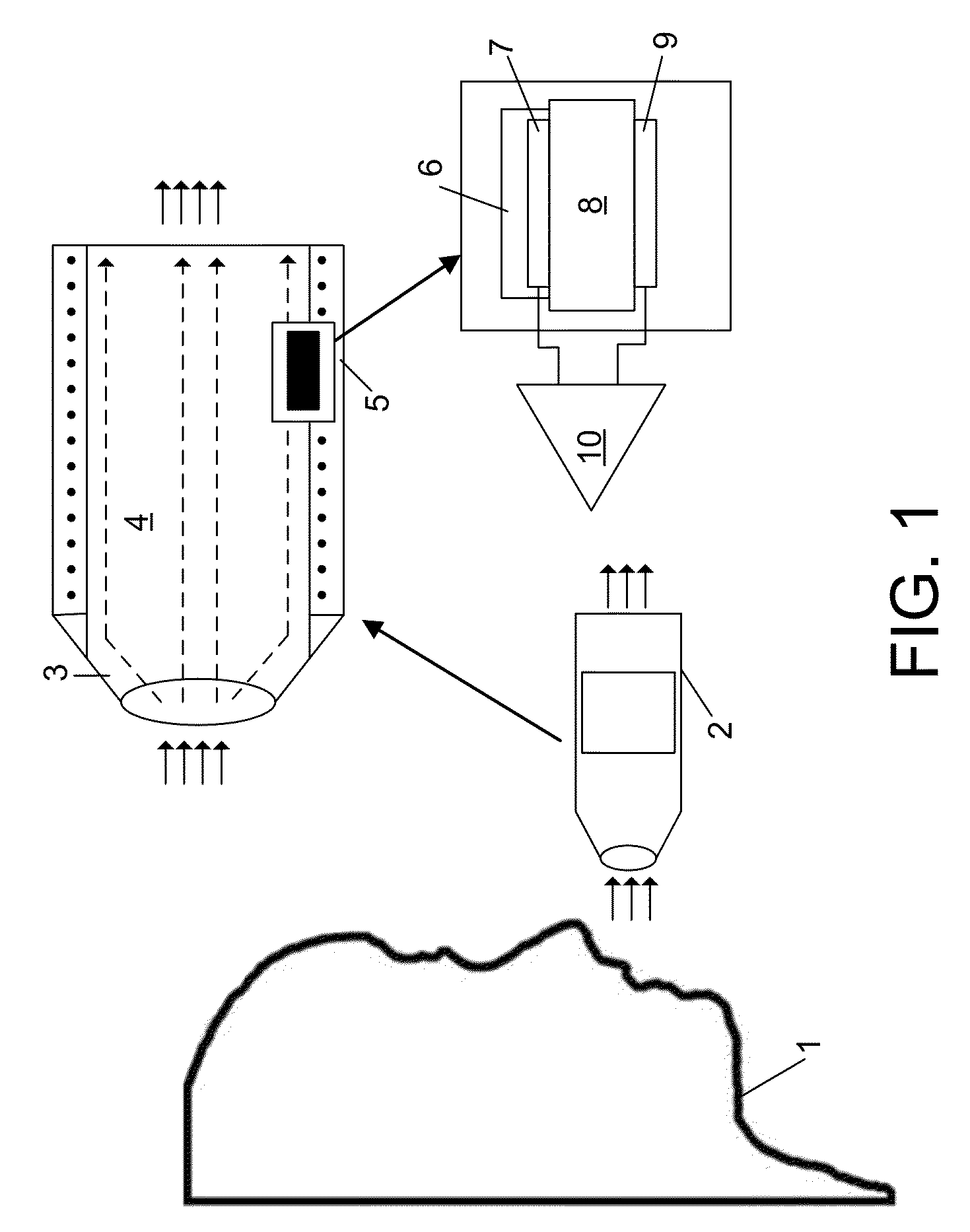
Thermal piezoelectric sensor for characterizing analytes in breath and related method
a piezoelectric sensor and analytes technology, applied in the direction of instruments, chemical methods analysis, material electrochemical variables, etc., can solve the problems of low compliance, non-invasive disease monitoring and management, and urine analysis, while non-invasive, have been criticized as inaccura
- Summary
- Abstract
- Description
- Claims
- Application Information
AI Technical Summary
Benefits of technology
Problems solved by technology
Method used
Image

Examples
example 1
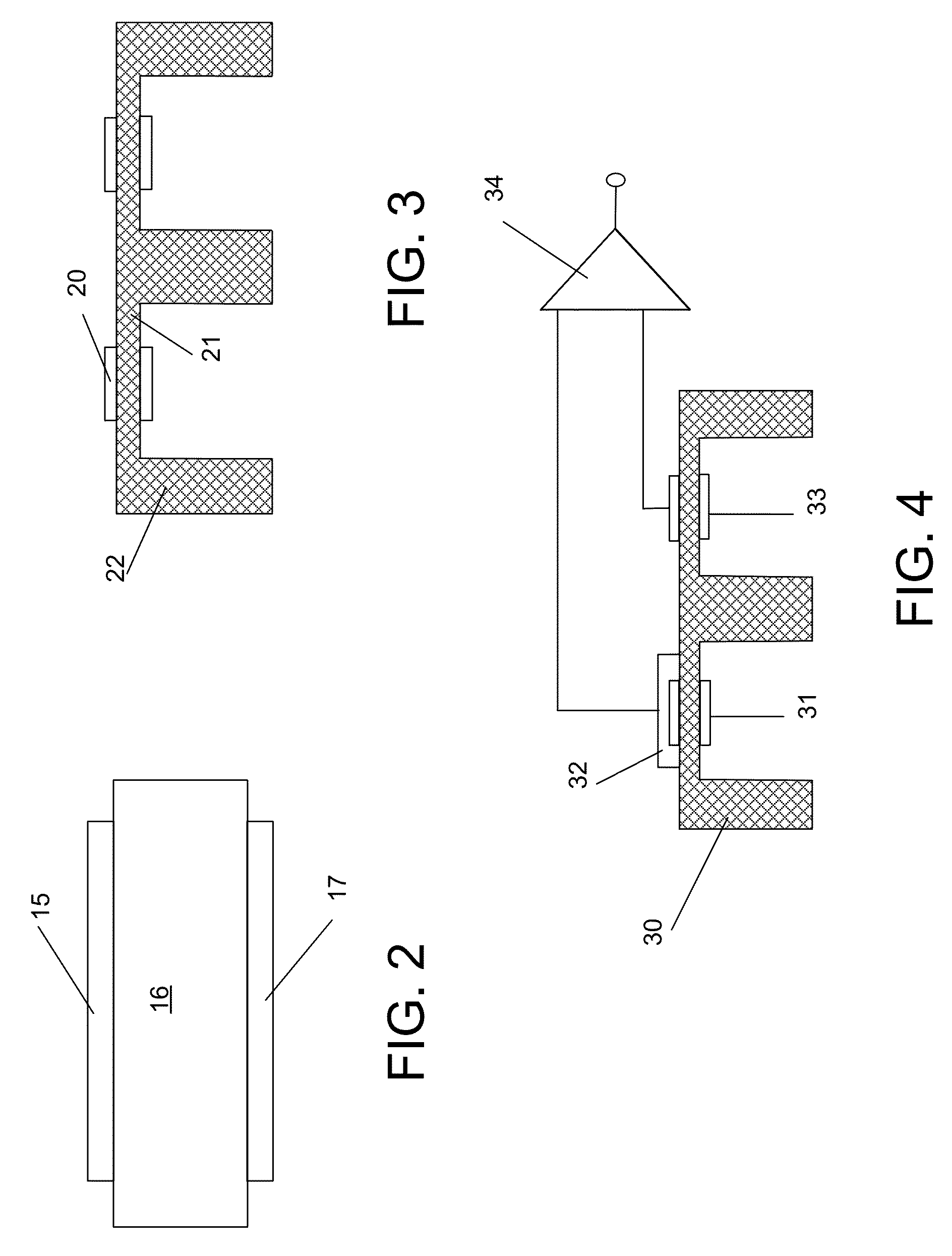
[0131]Shear-mode quartz resonators made from certain crystal cuts can be used as very sensitive temperature sensors. Table 2 lists the temperature sensitivity of the resonance frequency as a function of temperature for different quartz crystal cuts, according to Vig et. al., “Uncooled IR Imaging Array Based on Quartz Microresonators,” 1996 Journal of Microelectromechanical Systems, pgs. 131-136, June 1996, which is incorporated herein by reference. This phenomenological sensitivity of quartz crystals represents 1-3 orders of magnitude improvement in temperature sensitivity in comparison to other similar temperature dependent phenomena such as the Seebeck effect on which a thermopile device is based or thermistor. Thus, quartz crystal resonators can be configured as high performance thermal sensors.
[0132]
TABLE 2Temperature dependence of the resonance frequency of different cuts of quartz.Temperature Dependence of the ResonanceQuartz Crystal CutFrequency (ppm / ° C.)AC-Cut20LC-Cut35.4Y-...
example 2
[0138]Y-cut quartz resonator arrays with pixel size of 1 mm diameter and pixel thickness of 18.5 μm have been fabricated. Using an impedance analyzer coupled with a multiplexer, four pixels were simultaneously monitored for their performance. The impedance spectrum of the 89 MHZ Y-cut quartz resonator is shown in FIG. 6.
[0139]The fabricated resonator array was then calibrated for temperature sensitivity in an oven. The temperature inside the oven was monitored using two thermocouples, one mounted on the walls of the oven and the other located in close proximity to the resonator in the center of the oven. Calibration was performed over the temperature range of room temperature to ˜38° C. Frequency calibration at higher temperatures was not investigated because, for the intended applications, the calorimeter is expected to monitor reactions which produce small amounts of heat and the overall temperature of the resonator is not expected to go beyond ˜38° C. FIG. 7 shows a graph of the ...
PUM
| Property | Measurement | Unit |
|---|---|---|
| Thickness | aaaaa | aaaaa |
| Temperature | aaaaa | aaaaa |
| Concentration | aaaaa | aaaaa |
Abstract
Description
Claims
Application Information
 - R&D
- Intellectual Property
- Life Sciences
- Materials
- Tech Scout
- Unparalleled Data Quality
- Higher Quality Content
- 60% Fewer Hallucinations
Browse by: Latest US Patents, China's latest patents, Technical Efficacy Thesaurus, Application Domain, Technology Topic, Popular Technical Reports.
© 2025 PatSnap. All rights reserved.Legal|Privacy policy|Modern Slavery Act Transparency Statement|Sitemap|About US| Contact US: help@patsnap.com