Method for manufacturing positive electrode active material for power storage device
a technology of active materials and power storage devices, which is applied in the manufacture of final products, natural mineral layered products, silicates, etc., can solve the problems of reduced electron conductivity, limited charging capacity, and high operation voltage, and achieve excellent capacitance characteristics, electron conductivity, and further electron conductivity improvement
- Summary
- Abstract
- Description
- Claims
- Application Information
AI Technical Summary
Benefits of technology
Problems solved by technology
Method used
Image
Examples
embodiment 1
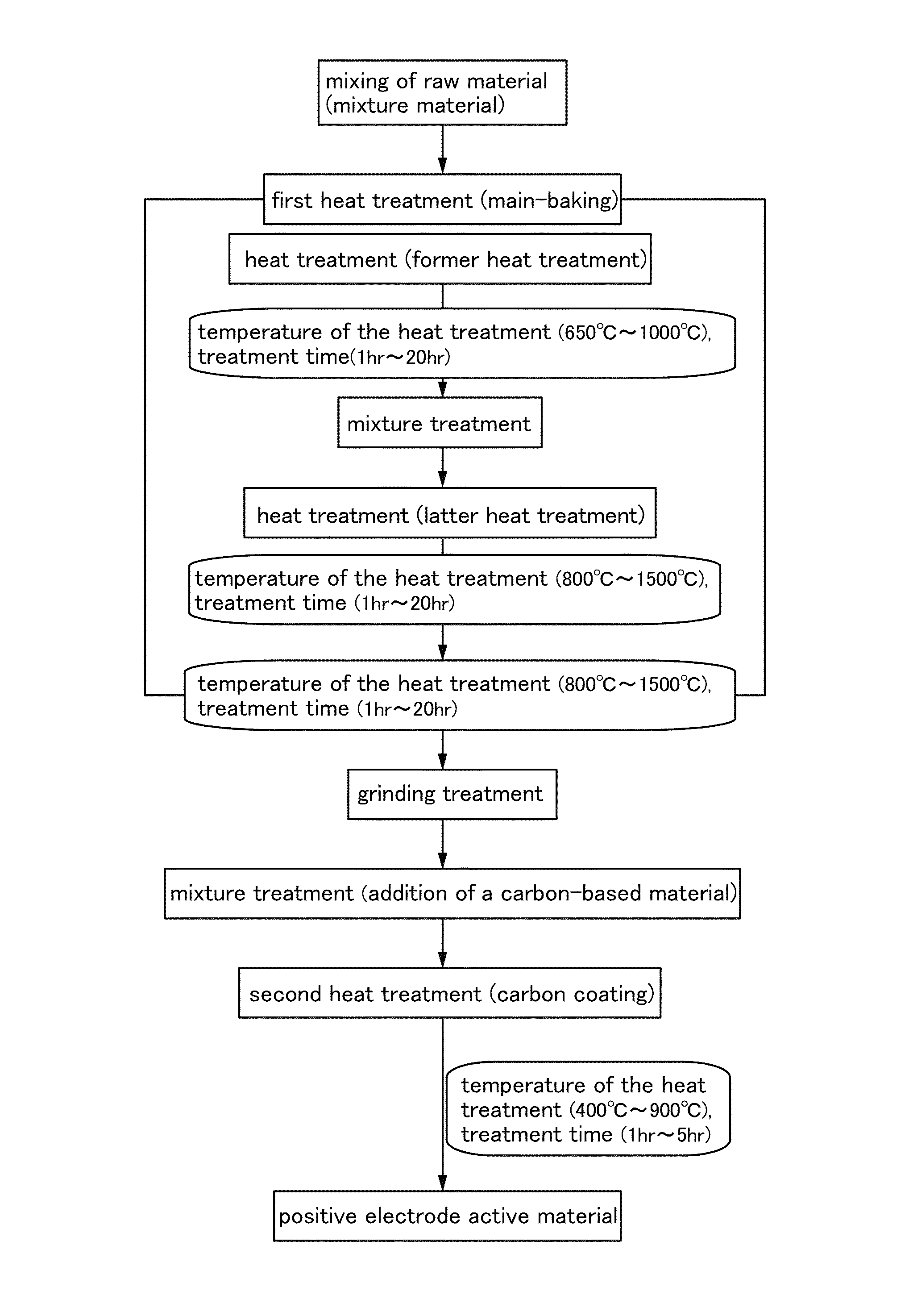
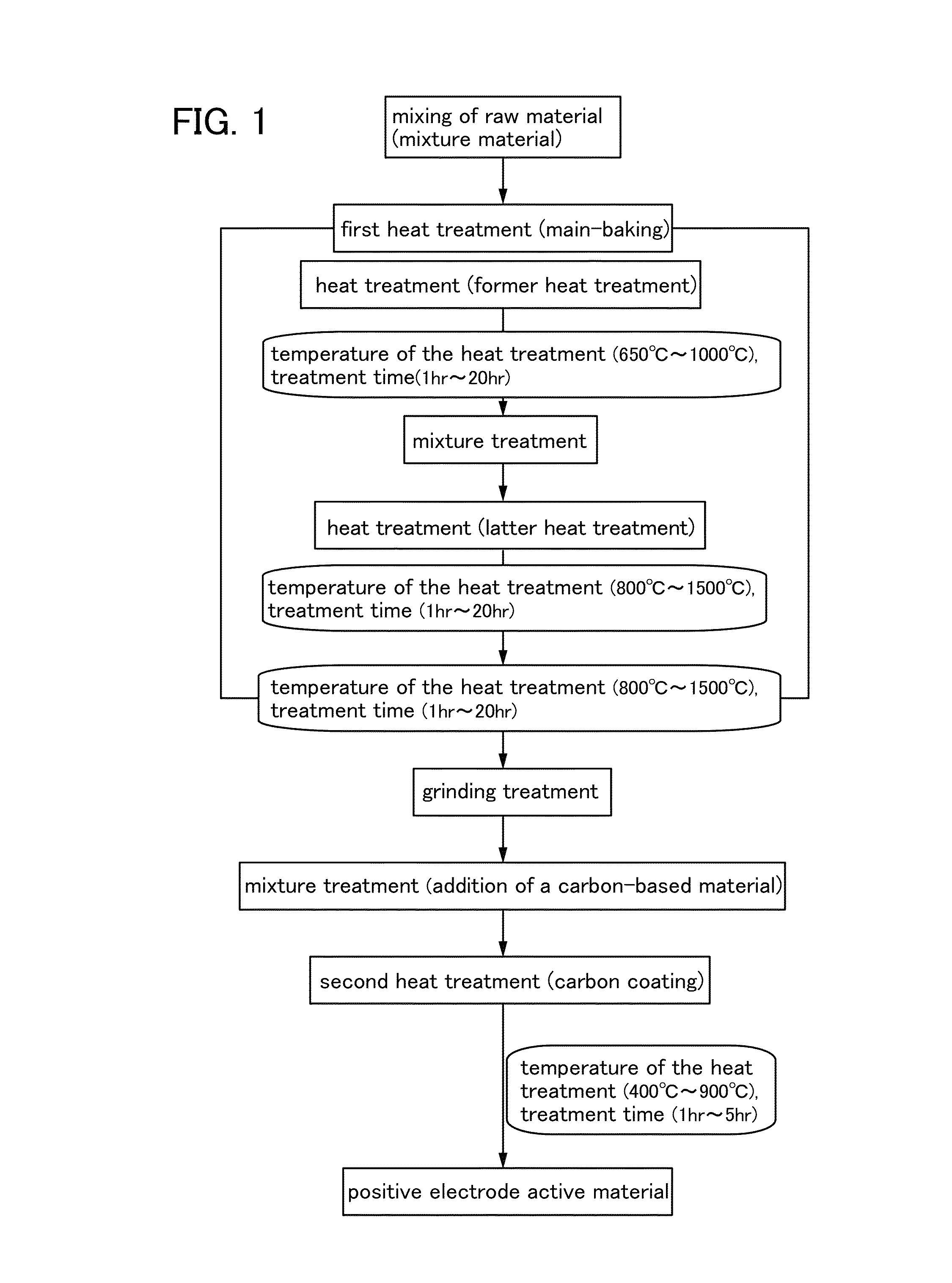
[0023]In this embodiment, an example of a method for manufacturing a positive electrode active material for a power storage device will be described. More specifically, in this embodiment, an example of a method for manufacturing a positive electrode active material for a power storage device, which includes a lithium silicate compound represented by a general formula Li2MSiO4, by a solid phase reaction method will be described.
[0024]In the above general formula, M represents one or more metal elements selected from transition metals such as manganese (Mn), iron (Fe), cobalt (Co), nickel (Ni), and the like.
[0025]First, a compound containing lithium which supplies Li in Li2MSiO4, a compound containing silicon which supplies Si in Li2MSiO4, and a compound containing a transition metal element which supplies M in Li2MSiO4 and is selected from transition metals such as manganese, iron, cobalt, and nickel are mixed, so that a mixture material is formed.
[0026]As the compound containing li...
embodiment 2
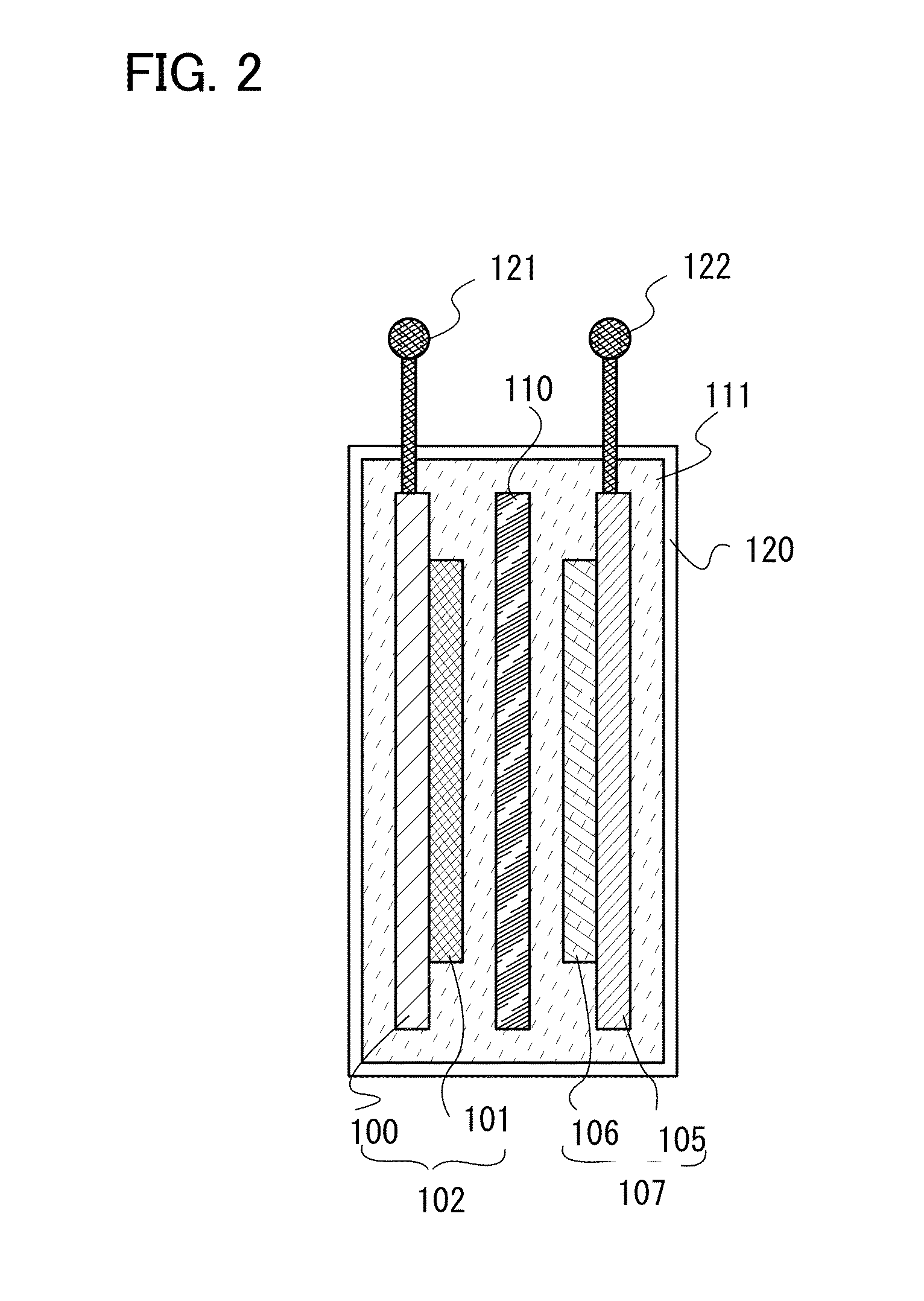
[0047]In this embodiment, a lithium-ion secondary battery will be described as one embodiment of a power storage device in which a positive electrode active material for a power storage device, which is obtained through the manufacturing process in Embodiment 1, is used. The schematic structure of the lithium-ion secondary battery is illustrated in FIG. 2.
[0048]In the lithium-ion secondary battery illustrated in FIG. 2, a positive electrode 102, a negative electrode 107, and a separator 110 are provided in a housing 120 which isolates the components from the outside, and the housing 120 is filled with an electrolyte solution 111. The separator 110 is provided between the positive electrode 102 and the negative electrode 107. Note that in this specification, a positive electrode active material layer 101 and a positive electrode current collector 100 over which the positive electrode active material layer 101 is formed are collectively referred to as the positive electrode 102. In ad...
embodiment 3
[0068]In this embodiment, application of a power storage device according to one embodiment of the present invention will be described.
[0069]The power storage device can be provided in a variety of electronic devices.
[0070]For example, the power storage device can be provided in cameras such as digital cameras or video cameras, mobile phones, portable information terminals, e-book terminals, portable game machines, digital photo frames, audio reproducing devices, and the like. Moreover, the power storage device can be provided in electrically propelled vehicles such as electric vehicles, hybrid vehicles, electric railway cars, working vehicles, carts, wheelchairs, and bicycles.
[0071]The characteristics of the power storage device according to one embodiment of the present invention are improved; for example, higher capacitance and a higher charging and discharging rate are obtained. By improving the characteristics of the power storage device, the power storage device can also be co...
PUM
| Property | Measurement | Unit |
|---|---|---|
| temperature | aaaaa | aaaaa |
| temperature | aaaaa | aaaaa |
| temperature | aaaaa | aaaaa |
Abstract
Description
Claims
Application Information
 - R&D
- Intellectual Property
- Life Sciences
- Materials
- Tech Scout
- Unparalleled Data Quality
- Higher Quality Content
- 60% Fewer Hallucinations
Browse by: Latest US Patents, China's latest patents, Technical Efficacy Thesaurus, Application Domain, Technology Topic, Popular Technical Reports.
© 2025 PatSnap. All rights reserved.Legal|Privacy policy|Modern Slavery Act Transparency Statement|Sitemap|About US| Contact US: help@patsnap.com


