Miniaturized pipe inspection system for measuring corrosion and scale in small pipes

a technology of inspection system and miniature pipe, which is applied in the direction of material analysis using wave/particle radiation, x/gamma/cosmic radiation measurement, instruments, etc., can solve the problems of time-consuming and insufficient information, limitation of the size of radiographic films that can be used, and the inability of the technique to predict which pipe has the defect, etc., to achieve high sensitivity

Inactive Publication Date: 2015-04-28
KING ABDULAZIZ UNIV
View PDF10 Cites 3 Cited by
  • Summary
  • Abstract
  • Description
  • Claims
  • Application Information

AI Technical Summary

Benefits of technology

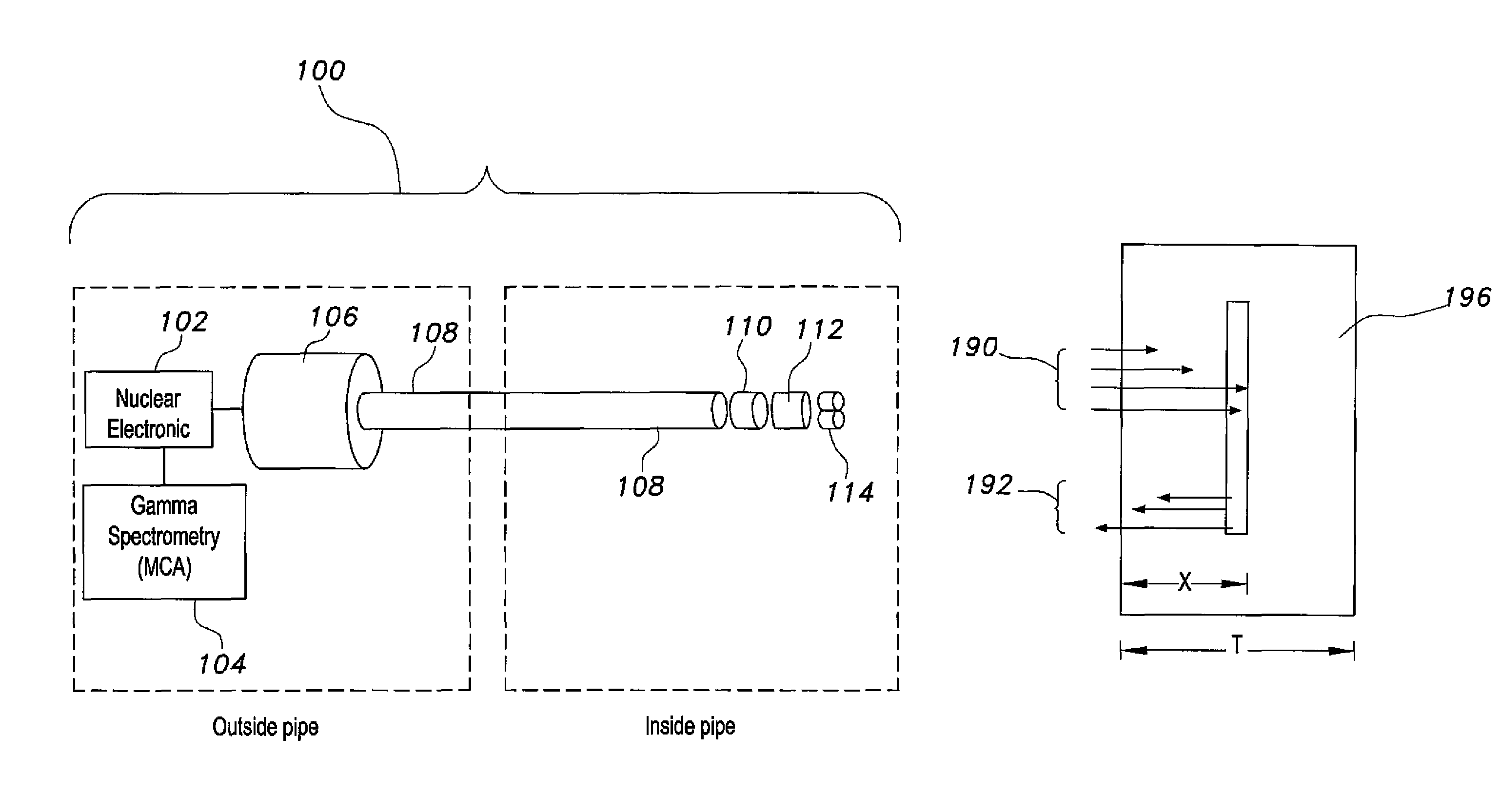
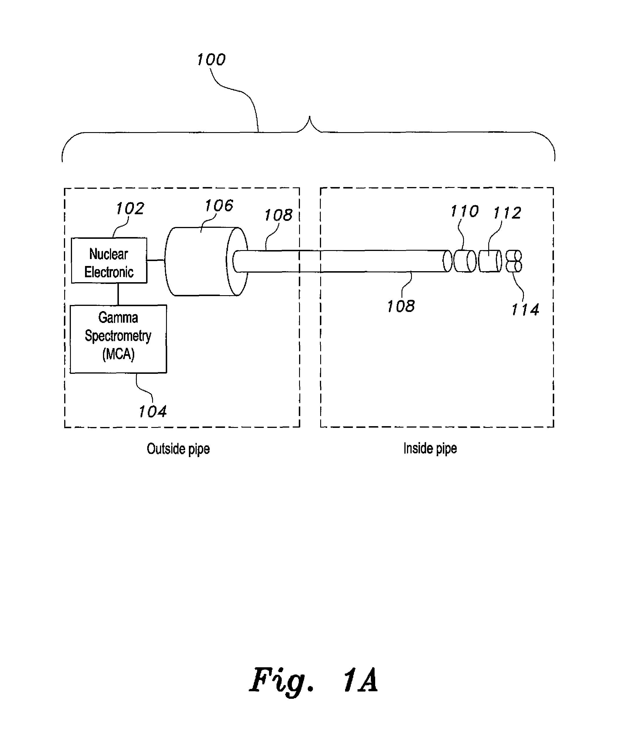
[0010]A light pipe is connected to the scintillation detector to transfer a light signal to a PMT (photomultiplier tube), gamma spectrometry devices, and nuclear electronics put outside the pipe for analyzing the back-scattered gamma rays. Because high detection sensitivity is used, only very small radioactivity on the order of micro-curies is used. Gamma rays interact with the pipe wall, and scattered radiation is measured by the scintillation detector. The amount of backscattered radiation is proportional to the pipe wall thickness and / or density. Each primary radiation produces its own scattered peak that can be separated from other scattered peaks or primary peaks by the gamma analysis system. Each backscatter peak counts, as well as total backscatter peak counts, provides information on corrosion, erosion, or deposits in the pipes. This provides higher accuracy and reliability and diversity of application of the system for pipes of different thicknesses and material.
[0012]A shield may or may not be put between the radioactive source of gamma rays and the scintillation detector. The system has high sensitivity for wider range of pipe wall thicknesses and materials and does not need surface preparation.

Problems solved by technology

This technique is time-consuming and does not provide adequate information, and has a limitation on the size of radiographic films that can be used.
Moreover, a high radioactivity source, on the order of many Curies, is usually used, which is associated with radiation hazard in the inspection process.
Besides being time-consuming, this technique cannot predict which pipe has the defect, the one in which the source is inserted or the one in which the detector is inserted.
And because Geiger counters are gas-filled detectors, it usually has very low efficiency, typically several orders of magnitude compared to solid scintillation detectors.
Moreover, Geiger detectors are counters only, providing no information on the spectrum of attenuated rays, and indiscriminately responding to both direct and scattered radiation.
This tends to produce errors in the registered counts.
Radiation detectors / spectrometers, such as scintillation detectors, are more useful, but cannot be inserted inside small diameter tubes because the photo-multiplier tube (PMT) and associated electronics are often much larger in size than the tube diameter.
Solid state detectors are very expensive, and their associated electronic components are large, expensive, and not useful for field work.
Again, this technique can be used in large sewage buried pipes, but cannot be used in pipes of heat exchangers.
Copper, nickel or iron, the material of the tubes, cannot be activated easily by a small neutron source because of their very small neutron absorption cross section.
Moreover, gamma rays need to be measured by high efficiency detectors that cannot be inserted inside heat exchangers.
Eddy current and ultrasound techniques can be used, but the inside of the pipe needs to be well prepared and clean, which makes the inspection process more difficult and time-consuming.
It should be clearly mentioned here that none of the existing techniques work for twisted pipes in heat exchangers.
Also, it is very difficult to use existing techniques for inspecting pipes whose cross section is not circular, or for inspecting bent pipes.

Method used


Image

  • Miniaturized pipe inspection system for measuring corrosion and scale in small pipes
  • Miniaturized pipe inspection system for measuring corrosion and scale in small pipes
  • Miniaturized pipe inspection system for measuring corrosion and scale in small pipes

Examples


Embodiment Construction

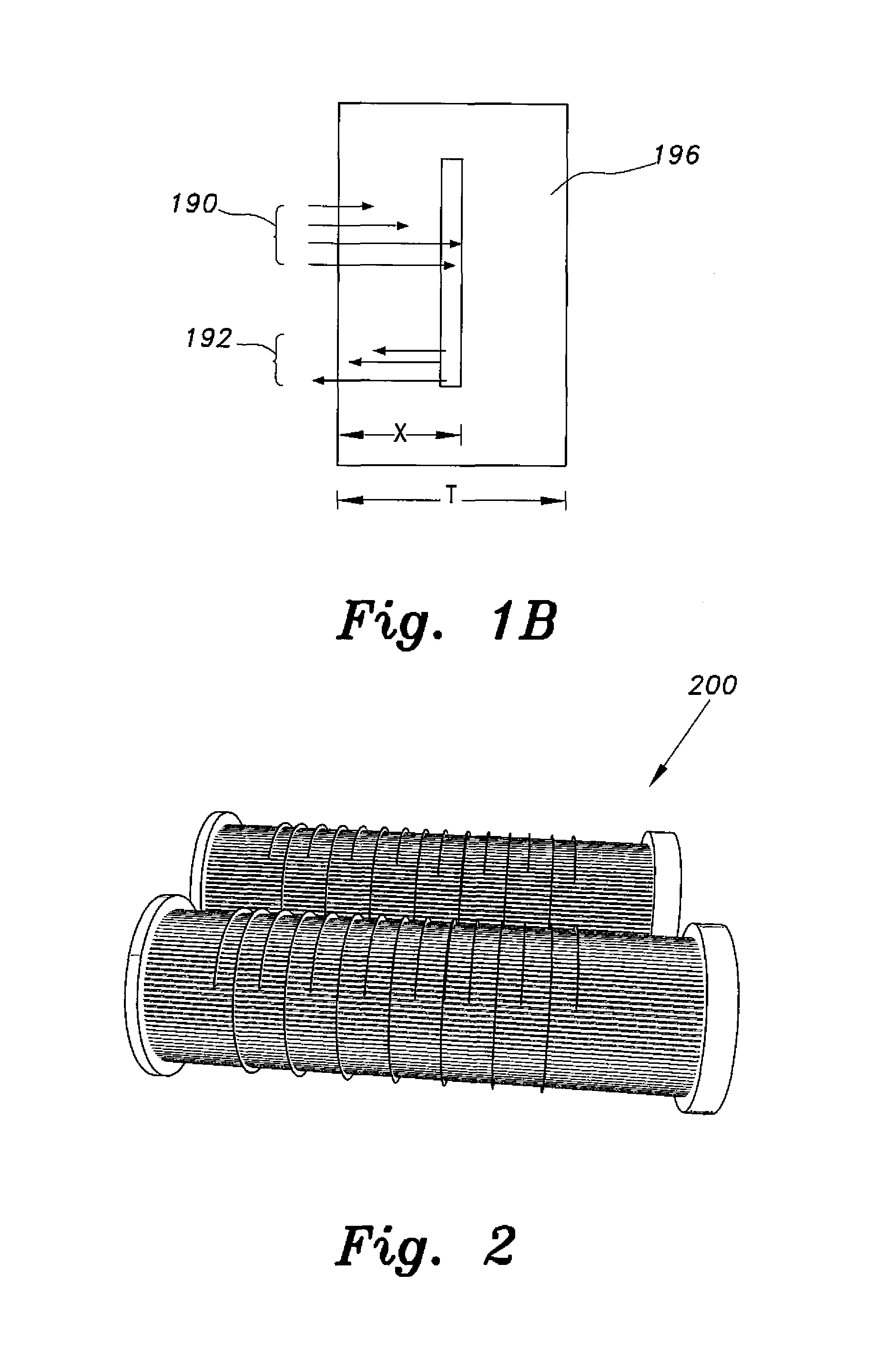
[0032]The miniaturized pipe inspection system 100 (shown in FIG. 1A) provides a system for inspecting twisted pipes, pipes whose cross sections are not circular, circular pipes, prepared or unprepared pipes, straight pipes, and bended pipes from the inside the pipe for heat exchangers, such as the heat exchanger tube bundle 200 shown in FIG. 2, or similar pipes. Referring to FIG. 1B, when gamma rays 190 are caused to be incident on a pipe wall 196, attenuation takes place in incident rays as well as the reflected gamma rays 192. The magnitude of attenuation depends on the energy of the gamma rays and the atomic number and density of the material. The attenuation to distance X of incident gamma rays 190 within the wall for a parallel beam is proportional to:

Exp(−μX),  (1)

where μ is the linear attenuation coefficient of the incident ray. A portion of the intensity is scattered due to Compton interaction. Characteristic x-rays, as well as annihilation radiation of 0.511 MeV, are also e...


PUM

PropertyMeasurementUnit
diametersaaaaaaaaaa
energyaaaaaaaaaa
diameteraaaaaaaaaa

Abstract

The miniaturized pipe inspection system for measuring corrosion and scale in small pipes utilizes scattered radiation, which is measured by high efficiency solid scintillation gamma detector / spectrometer inserted inside the tube and separated from its bulky photomultiplier tube (PMT) and associated electronics by light pipe or fiber optic cable whose diameter can be very small. The light signal produced in the scintillation material is transmitted through the light pipe to outside the pipe to be inspected, where a PMT and electronic components including gamma ray energy analyzers are located. Gamma spectroscopy combined with gamma counting allows for multiple gamma ray primary and multiple backscattered radiation, thereby yielding high accuracy and high reliability of obtained corrosion, erosion and deposits data.

Description

BACKGROUND OF THE INVENTION[0001]1. Field of the Invention[0002]The present invention relates to a system for conducting in situ and non-destructive measuring of the thickness of coatings, and more particularly to a miniaturized pipe inspection system for measuring corrosion and scale in small pipes that uses backscattering of gamma rays to inspect corrosion and scale substrates disposed inside small pipes, which may be twisted, bent, or have irregular cross-sections.[0003]2. Description of the Related Art[0004]To detect corrosion in small pipes, such as heat exchanger pipes, radiographic techniques are sometimes used in which one radioactive source is inserted inside one tube and radiographic film is inserted inside an adjacent or nearby tube. This technique is time-consuming and does not provide adequate information, and has a limitation on the size of radiographic films that can be used. Moreover, a high radioactivity source, on the order of many Curies, is usually used, which is...

Claims


Application Information

Patent Timeline
Patent Type & Authority Patents(United States)
IPC IPC(8): G01N23/203G01T1/36H01J40/16
CPCG01N23/203G01T1/362H01J40/16
Inventor ALZAIDI, SAMIR ABDUL-MAJID
Owner KING ABDULAZIZ UNIV
Why Eureka
Try Eureka