Anti-fouling surface, and radiation source assembly and fluid treatment system comprising same

a technology of radiation source and fluid treatment system, which is applied in the field of anti-fouling surface, can solve the problems of affecting the ability of the fluid to transmit uv radiation, affecting the efficiency of the fluid treatment system, and the cost of cleaning the sleeves about the radiation source, so as to reduce the frequency of mechanical cleaning, reduce the rate of accumulation of fouling on the surface, and reduce the effect of surface acidity

Inactive Publication Date: 2015-05-12
TROJAN TECH
View PDF11 Cites 1 Cited by
  • Summary
  • Abstract
  • Description
  • Claims
  • Application Information

AI Technical Summary

Benefits of technology

[0032]Accordingly, in one of its aspects, the present invention provides an element having an immersible portion for contact with an aqueous liquid, the immersible portion comprising a contact surface which is for contact with the aqueous liquid, the contact surface configured to have strong acidity.
[0035]Thus, the present inventor has discovered an approach which obviates or mitigates the rate of accumulation of fouling on surfaces in contact with aqueous solution, such as the protective (e.g., quartz) sleeves in an ultraviolet radiation fluid treatment system. This approach involves modifying at least a portion of the surface of those sleeves in contact with fluid (e.g., water) to have an inherent strong surface acidity. In some cases, this can obviate the need for complex mechanical cleaning equipment or at least result in a reduced frequency of mechanical cleaning.
[0036]In a preferred embodiment, a strong and permanent surface acidity is achieved via the immobilization of a solid acid in a relatively thin film (e.g., a thickness in the range of from about 1 molecular layer to about 1 μm). The solid acid may be either grafted or otherwise deposited directly onto the surface of the protective (e.g., quartz) sleeve or grafted or otherwise deposited onto one or more thin films which are deposited onto the protective (e.g., quartz sleeve).
[0037]While not wishing to be bound by any particular theory or mode of action, it is believed that the strong surface acidity shifts the local pH in the interfacial region between the surface of the protective (e.g., quartz) sleeve and the fluid (e.g., aqueous liquid) to a sufficiently low value that inorganic compounds (e.g., metal salts) will remain soluble and will not crystallize on the surface of the protective (e.g., quartz) sleeve. In addition, it is believed that the strong local acidity creates an environment hostile to microbial life forms and thus the protective (e.g., quartz) sleeve is imbued with an inherent antimicrobial property. In this way, it is believed that the build-up of fouling materials on the protective (e.g., quartz) sleeve is obviated or mitigated.

Problems solved by technology

Depending on the quality of the fluid which is being treated, the sleeves surrounding the UV lamps periodically become fouled with foreign materials, inhibiting their ability to transmit UV radiation to the fluid.
This practice was regarded by many in the field as inefficient, labourious and inconvenient.
In many cases, once installed, one of the largest maintenance costs associated with prior art fluid treatment systems is often the cost of cleaning the sleeves about the radiation sources.
When these fluid treatment systems have been implemented there is an ongoing problem of build-up of fouling materials on the exterior surface of the radiation sources.
First, seal failure in the cleaning system taught by the Maarschalkerweerd #2 Patents can occur resulting in the loss of acidic cleaning fluid and a reduced capacity to remove the foulant as well as the introduction of the cleaning chemicals to the environment.
Second, the cleaning system is relatively complex resulting in significant capital and operating costs associated with the equipment.
Third, the mechanical cleaning equipment occupies space in the reactor which requires the UV lamps to have a minimum separation distance, which reduces the effectiveness of disinfection and lowers the efficiency of the ultraviolet radiation reactor.
Fourth, the wiping action can cause scratches in the sleeves which may potentially promote fouling or lead to premature failure of the sleeve.
Fifth, the moving parts required in the design may also lead to failure and maintenance requirements.
Lastly, regardless of mechanical wiping, the sleeves ultimately must be removed for either cleaning and or replacement, which is time consuming and undesirable.
Apparently, this substantially increases the solubility of inorganic compounds (e.g., metal salts) which would otherwise precipitate onto the sleeve.
However, the utility of the Herrington approach for prevention of ultraviolet radiation source assembly fouling is questionable.
Furthermore, the process requires the consumption of additional energy at great cost to achieve the passive cleaning process.
Herrington suggests that diamonds may be used to improve electrical contact with the quartz surface—this is obviously an impractical and costly solution.
It is also possible that the wrapping of a metal wire about a quartz sleeve may exacerbate fouling by trapping debris.
However, in each of these approaches, the abrasive material must be recovered from the decontaminated water, which requires material separation, material handling and the associated capital and operating costs.
Most undesirable is the fact that the introduction of acid to the water will necessitate a downstream neutralization step or another means to recover the acid from the decontaminated water before discharge to the environment.

Method used


Image

  • Anti-fouling surface, and radiation source assembly and fluid treatment system comprising same
  • Anti-fouling surface, and radiation source assembly and fluid treatment system comprising same
  • Anti-fouling surface, and radiation source assembly and fluid treatment system comprising same

Examples


example 1

Preparation Of An Acid Functionalized Quartz Surface

[0122]Two coupons (1 inch×1 inch×1 mm) made of GE 214 quartz (fused silica) (Pelco International, p / n 26013) were chemically cleaned by immersion in toluene for 20 minutes in a manner that exposed both major surfaces to the fluid. The specimens were then rinsed with anhydrous 2-propanol and dried. The specimens were similarly immersed in hydrochloric acid, 10% (v / v) for 20 minutes and subsequently rinsed with deionised water and then with 2-propanol. The specimens were then immersed in toluene again for 20 minutes and subsequently rinsed thoroughly with 2-propanol.

[0123]The specimens were then immobilized in a reactor and activated at 120° C. for 2 hours in the presence of air (ultra zero gas) flowing over the specimens. After the reaction was completed, the reactor was cooled to room temperature, isolated and transferred into a glove box without exposing the specimens to the ambient. The glove box was purged several times using ul...

example 2

Fouling Study In A Laboratory Apparatus

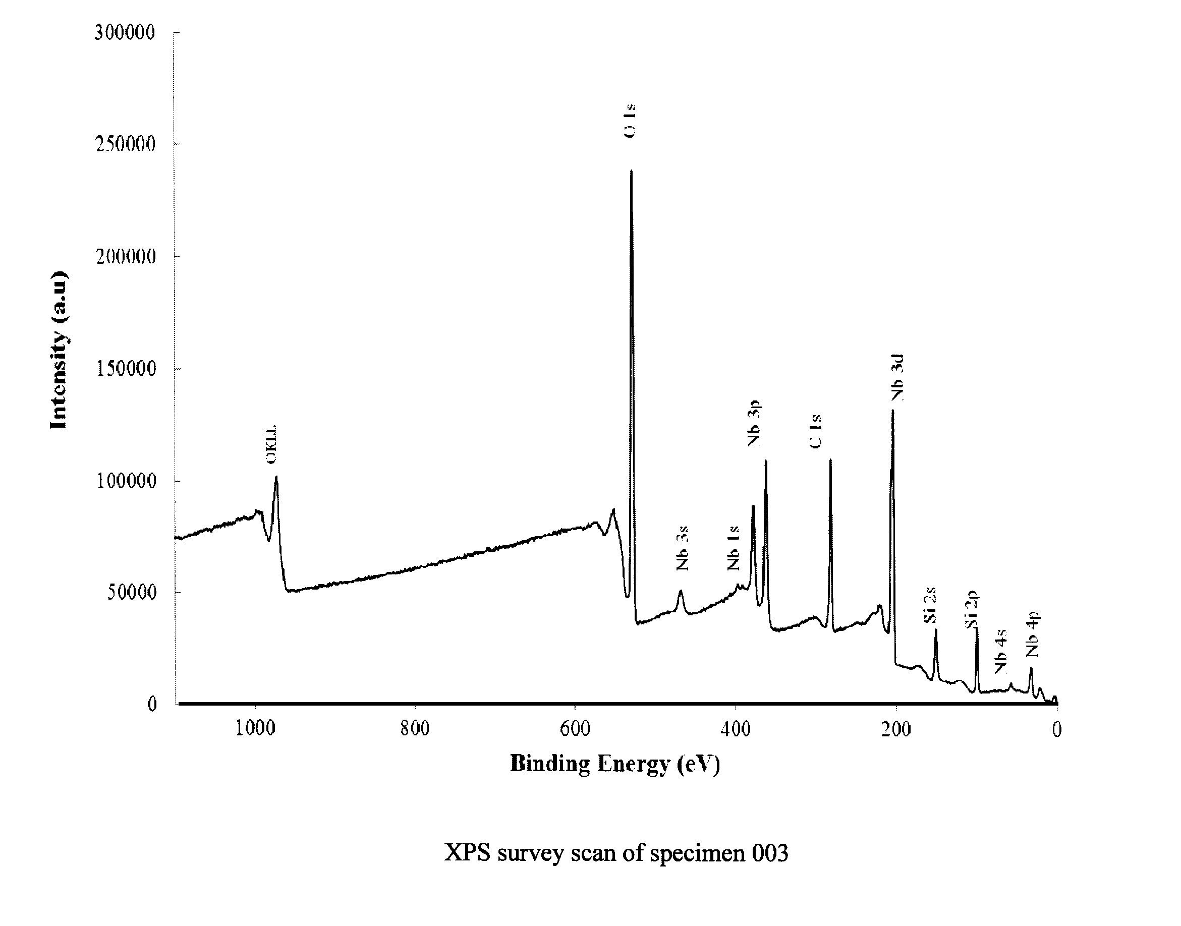
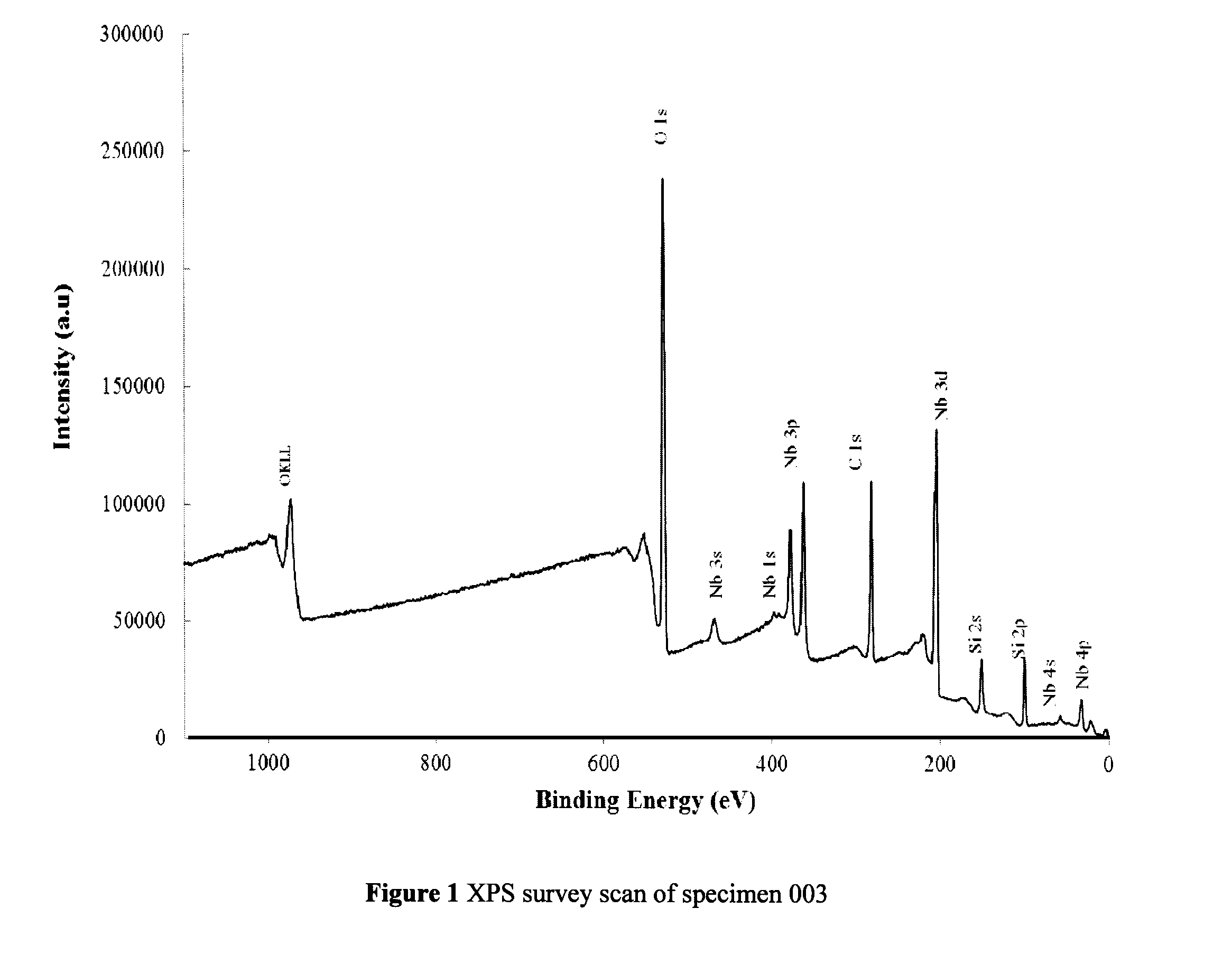
[0127]Six research specimens consisting of GE214 quartz coupons were acid functionalized as described in example 1 in a manner yielding highly dispersed niobium oxide nanoparticles over the quartz surface with overlayer thicknesses of approximately 1 nm. Four untreated but chemically cleaned quartz coupons were used as control specimens. The UV transmittance (UVT) of monochromatic light of 254 nm was measured at 20 locations through all 10 specimens using a Varian Cary 100 UV-Visible (UV-Vis) spectrophotometer equipped with an integrating sphere (Labsphere, North Sutton, N.H., USA). The 10 specimens were subsequently immobilized within 10 individual flow cells with calming zones of 20 hydraulic diameters upstream and 10 hydraulic diameters downstream of the quartz specimens, to ensure fully developed turbulent flow through the duct of the flow cell.

[0128]The specimens were exposed to a proprietary synthetic fouling water at a Reynolds number of...


PUM

PropertyMeasurementUnit
thicknessaaaaaaaaaa
thickaaaaaaaaaa
temperatureaaaaaaaaaa

Abstract

An element having an immersible portion for contact with an aqueous liquid, the immersible portion having a contact surface for contact with the aqueous liquid, the contact surface configured to have strong acidity, a radiation (e.g., ultraviolet radiation) source assembly, a radiation (e.g., ultraviolet radiation) source module and a fluid (e.g., water) treatment system incorporating this element applicable to any surface in contact with fluid that is susceptible to build-up of fouling materials. The embodiments obviate or mitigates the rate of accumulation of fouling on surfaces in contact with aqueous solution, such as the protective (e.g., quartz) sleeves in an ultraviolet radiation fluid treatment system, by modifying at least a portion of the surface of those sleeves in contact with fluid (e.g., water) to have an inherent strong surface acidity.

Description

CROSS-REFERENCE TO RELATED APPLICATION[0001]The present application claims the benefit under 35 U.S.C. §119(e) of provisional patent application Ser. No. 61 / 457,646, filed May 6, 2011, the contents of which are hereby incorporated by reference.BACKGROUND OF THE INVENTION[0002]1. Field of the Invention[0003]In one of its aspects, the present invention relates to an antifouling surface—e.g., a quartz element having an antifouling surface. In another of its aspects, the present invention relates to a radiation source assembly comprising the antifouling surface. In yet another of its aspects, the present invention relates to a radiation source module comprising the antifouling surface. In yet another of its aspects, the present invention relates to a fluid treatment system comprising the antifouling surface. In another of its aspects, the present invention relates to a method of producing an antifouling surface—e.g., a quartz element having an antifouling surface. Other aspects of the i...

Claims


Application Information

Patent Timeline
Patent Type & Authority Patents(United States)
IPC IPC(8): B32B9/00B05D3/00B08B17/00C02F1/32C02F1/66C09D5/16
CPCC02F1/325B08B17/00C09D5/1618C02F1/66C02F2201/3228C02F2303/14C02F2303/20C02F2303/22Y10T428/1359Y10T428/259C02F1/32
Inventor O'KEEFE, WILLIAM KEVIN
Owner TROJAN TECH
Why Eureka
Try Eureka