Biocompatible and photocurable polymers

a biocompatible and photocurable technology, applied in the field of solid substrates, can solve the problems of insufficient sample amounts or non-uniform distribution over the chip surface, insufficient sample amounts or unsuitable mechanical contact printing, inability to detect barcodes, etc., and achieve the effect of rapid detection rate and rapid detection of fluorescence beads

Active Publication Date: 2016-02-09
APPLIED BIOCODE
View PDF7 Cites 11 Cited by
  • Summary
  • Abstract
  • Description
  • Claims
  • Application Information

AI Technical Summary

Benefits of technology

[0019]In a further aspect of the present invention, the combination of low background in absorbance or fluorescence of EPON 1002F epoxy resin and convenience in processing by blending functional monomer in the photoresist formulation was especially emphasized.
[0055]In a further aspect of the present invention, the digital barcode beads have paramagnetic properties, that is, they have magnetic property when placed within a magnetic field, but retain no residual magnetism when removed from the magnetic field. Magnetic beads allow washing in a microplate by collection of beads with an external magnet, and resuspension of beads when the magnetic field is removed. Multiple digital magnetic beads allow multiplexed assays to be performed in a single well.

Problems solved by technology

However, mechanical contact printing is not very desirable because it prints one spot per contact that results in relatively large printing variations from spot to spot or batch to batch, inconsistent spot morphology, misprinting, and slide surface variations, all of which are undesirable for DNA microarray analysis.
Further, distributing a small volume of liquid samples over a relatively large chip surface often encounters the problems of insufficient sample amounts or non-uniform distribution over the chip surface.
These problems can cause incomplete reactions or very long reaction time.
The problems of reflection configuration are (1) it is difficult to setup the collection optics in proper position, especially when the bead dimensions are on a micrometer scale, and (2) the light collection efficiency is poor and the barcode contrast is low, especially when micro beads are in the micro flow system.
The flow scatters light, which interferes with optical reflection or emissive detection.
Further, fluorescent beads, the spectral range and the possible number of spectrally distinguishable labels, however, often limit the potential number of code variations.
In addition, the validity of the coding signatures is another serious concern, since the incorporated coding elements in some cases may be lost; photo bleached, or interfered spectrally with the analytical signals.
In the case of multi-metal (Au, Pt, Ni, Ag, etc) color micro rods, the encoding scheme suffers from the difficulty of manufacturing and the number of colors, based on different metal materials, is limited.
Although high speed camera is available for capturing bar code images, pattern recognition is a slow and time consuming process.
Therefore, it is difficult to identify hundreds or thousands of beads in a short time to improve throughput.
Although photopolymers are commonly used in the semiconductor industry, many semiconductor industry photopolymers are not biocompatible because of the difficulty of immobilizing biomolecules, such as proteins, oligonucleotides or cells, on the surface of these materials, especially if long term stability is required for storage.
Other problems associated with current photoresists include high auto fluorescence, brittleness, and poor adhesive properties for multilayer formation.
Because the surface of SU-8 has epoxy groups it has hydrophobic properties and presents a limitation to many biological applications requiring specific functional groups.
These limitations include challenges in surface wetting, biofouling and limited cell attachment.

Method used


Image

  • Biocompatible and photocurable polymers
  • Biocompatible and photocurable polymers
  • Biocompatible and photocurable polymers

Examples


example 1

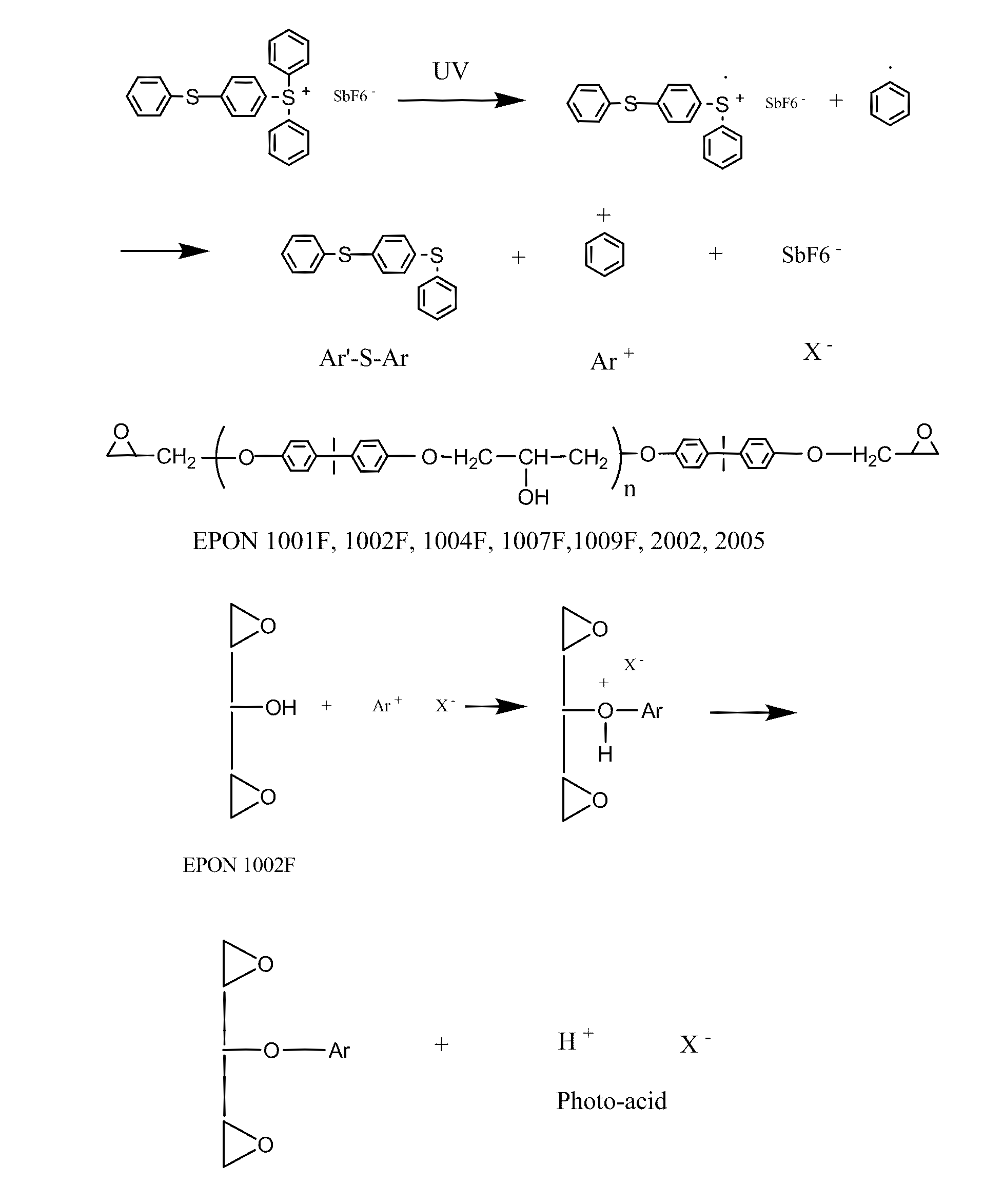
[0144]According to this example a control polymer solution was produced from the photoresist formulation of Table 1 and was cast onto clear polyester (mylar) film with 8-Path Wet Film Applicator. The film was dried in the ventilation hood for several hours, then further dried in forced ventilation oven at 45° C. for 30 minutes, then irradiated with UV (Stratalinker UV Crosslinker, Model 1800, 254 nm UV light bulbs, 8 watts each, power delivered ˜3000 μwatts / sqcm, total dose 300 mjoules / sqcm) for 100 seconds with or without photomask (4 in×4 in), then post baked at 65° C. for 3 minutes

[0145]

TABLE 1Photoresist formulation containing EPON SU-8 as controlComponent% by weightEPON SU-8 resin61.0Triarylsulfonium6.1hexafluoroantimonateCyclopentanone32.9Total100

example 2

[0146]According to this example a control polymer solution made from the photoresist formulation of Table 2 was cast onto clear polyester (mylar) film with 8-Path Wet Film Applicator. The film was dried in the ventilation hood for several hours, then further dried in forced ventilation oven at 45° C. for 30 minutes, then irradiated with UV (Stratalinker UV Crosslinker, Model 1800, 254 nm UV light bulbs, 8 watts each, power delivered ˜3000 μwatts / sqcm, total dose 300 mjoules / sqcm) for 100 seconds with or without photomask (4 in×4 in), then post baked at 65° C. for 3 minutes.

[0147]

TABLE 2Photoresist formulation containing EPON 1002F resin as controlComponent% by weightEPON 1002F resin61.0Triarylsulfonium6.1hexafluoroantimonateCyclopentanone32.9Total100

example 3

[0148]According to this example, acrylic acid was added into the photoresist formulation of Example 1 containing EPON SU-8 resin in different ratios (weight of acrylic acid / weight of photoresist solution=0.025, 0.05, 0.075, 0.1, 0.125). The resulting solution was cast onto clear polyester (mylar) film with 8-Path Wet Film Applicator. The film was dried in the ventilation hood for several hours, then further dried in forced ventilation oven at 45° C. for 30 minutes, then irradiated with UV (Stratalinker UV Crosslinker, Model 1800, 254 nm UV light bulbs, 8 watts each, power delivered ˜3000 μwatts / sqcm, total dose 300 mjoules / sqcm, for thicker film, double dose) for 100 seconds with or without photomask (4 in×4 in), then post baked at 65° C. for 3 minutes.


PUM

PropertyMeasurementUnit
diameteraaaaaaaaaa
diameteraaaaaaaaaa
thicknessaaaaaaaaaa

Abstract

The present invention relates to substrates for biological testing produced from photo-curable epoxy compositions which further include carboxyl-containing monomers such as acrylic acid, 2-carboxyethyl acrylic acid, 4-vinylbenzoic acid, or 3-Acrylamido-3-methyl-1-butanoic acid, or glycidyl methacrylate, etc. The photo-curable compositions may be used to cast films or fabricate beads, magnetic beads, or magnetic beads containing nickel barcodes. The resulting various kinds of films, beads, magnetic beads, or magnetic beads containing nickel barcodes may find use in clinical or biological applications.

Description

[0001]This application claims benefit of U.S. Provisional Application No. 61 / 195,565 filed Oct. 8, 2008 and further is a continuation-in-part application of U.S. patent application Ser. No. 12 / 069,720 which was filed Feb. 11, 2008 and further is a continuation-in-part of U.S. patent application Ser. No. 11 / 580,514, filed Oct. 13, 2006 now U.S. Pat. No. 7,858,307 and a continuation-in-part of U.S. patent application Ser. No. 11 / 502,606, filed Aug. 9, 2006, now U.S. Pat. No. 7,871,770 which claims the benefit of the priority of Provisional Patent Application No. 60 / 706,896, which was filed Aug. 9, 2005. This application is also a continuation-in-part of PCT / US08 / 08529, which was filed Jul. 11, 2008 which claims benefit of U.S. Provisional Patent Application No. 60 / 964,108, which was filed Aug. 8, 2007 the disclosures of which are hereby incorporated by reference, as if fully set forth herein.BACKGROUND OF THE INVENTION[0002]1. Field of the Invention[0003]The present invention relates ...

Claims


Application Information

Patent Timeline
Patent Type & Authority Patents(United States)
IPC IPC(8): C08F8/00C08F220/18G01N33/545C08F2/50G03F7/26C12Q1/68
CPCG01N33/545C08F2/50C08F220/18C12Q1/6813C12Q1/6846C08F8/00G03F7/26C12Q2563/155C12Q2563/107C08L63/10C08L63/00G03F7/038G01N27/745G03F7/085
Inventor HO, WINSTON Z.HOU, CHUNG-JEN
Owner APPLIED BIOCODE
Why Eureka
Try Eureka