
Differential capacitive readout system and method for infrared imaging

Active Publication Date: 2016-03-22
UNIV OF SOUTH FLORIDA
View PDF7 Cites 10 Cited by
  • Summary
  • Abstract
  • Description
  • Claims
  • Application Information

AI Technical Summary

Benefits of technology

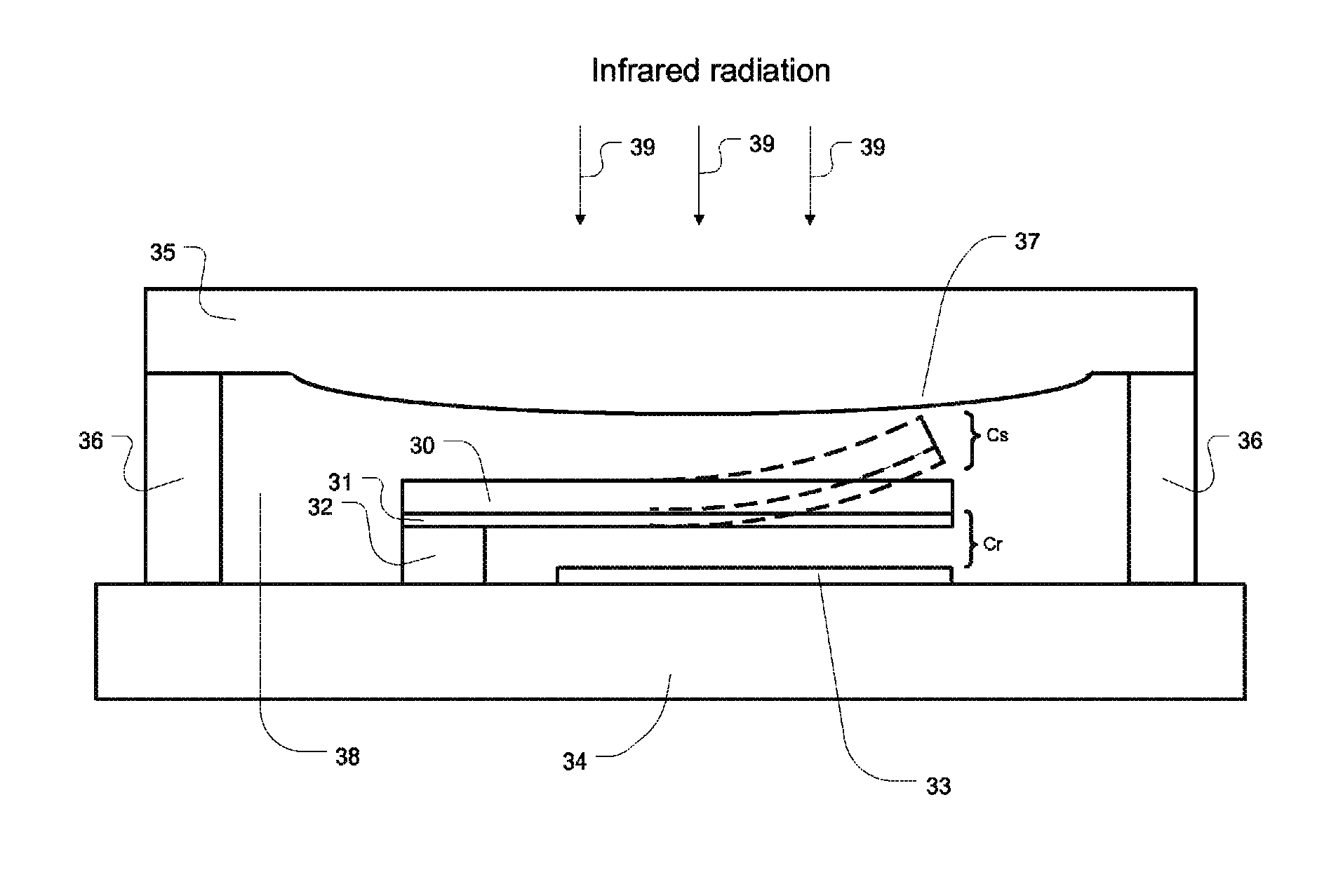
The present invention is a new IR imaging system that uses microelectromechanical systems and a special differential capacitive readout approach to achieve higher sensitivity. The system is packaged using wafer level packaging to minimize heat loss and reduce costs. A micromachined micro lens array is directly fabricated onto the packaging substrate to improve sensitivity. A traditional bimaterial cantilever or membrane is used as the moving sensor cell. The micro lens can be fabricated on the inner or outer surface of the sealing cap electrode and may be coated with an anti-reflection coating to minimize signal loss. Overall, this system offers improved performance and reduced cost compared to traditional IR sensors.

Problems solved by technology

Earlier IR cameras using HgCdTe or InSb electro-optic detectors are expensive, bulky, and inconvenient to use because of the need for cryogenic cooling in order to minimize thermal noise.
Quantum well IR detectors also require expensive cryogenic or Stirling engine cooling systems to increase their sensitivity.
Many of the existing examples of uncooled IR detectors use resistive or piezoresistive readout, and thereby suffer from higher power consumption and thermal resistive noise.
Uncooled pyroelectric and ferroelectric IR detectors require choppers to operate, adding complexity to the camera system.
Additionally, uncooled thermoelectric IR detectors have low responsivity.

Method used


Image

  • Differential capacitive readout system and method for infrared imaging
  • Differential capacitive readout system and method for infrared imaging
  • Differential capacitive readout system and method for infrared imaging

Examples


Embodiment Construction

[0025]The present invention provides an un-cooled capacitive MEMS IR detector with differential readout and wafer level packaged cavity and micro-lenses. The system taught herein will solve the problems of the prior designs, while exhibiting very low power consumption and lower noise level, much higher sensitivity, and also making the new IR imaging system smaller, cheaper, and more suitable for practical imaging applications.

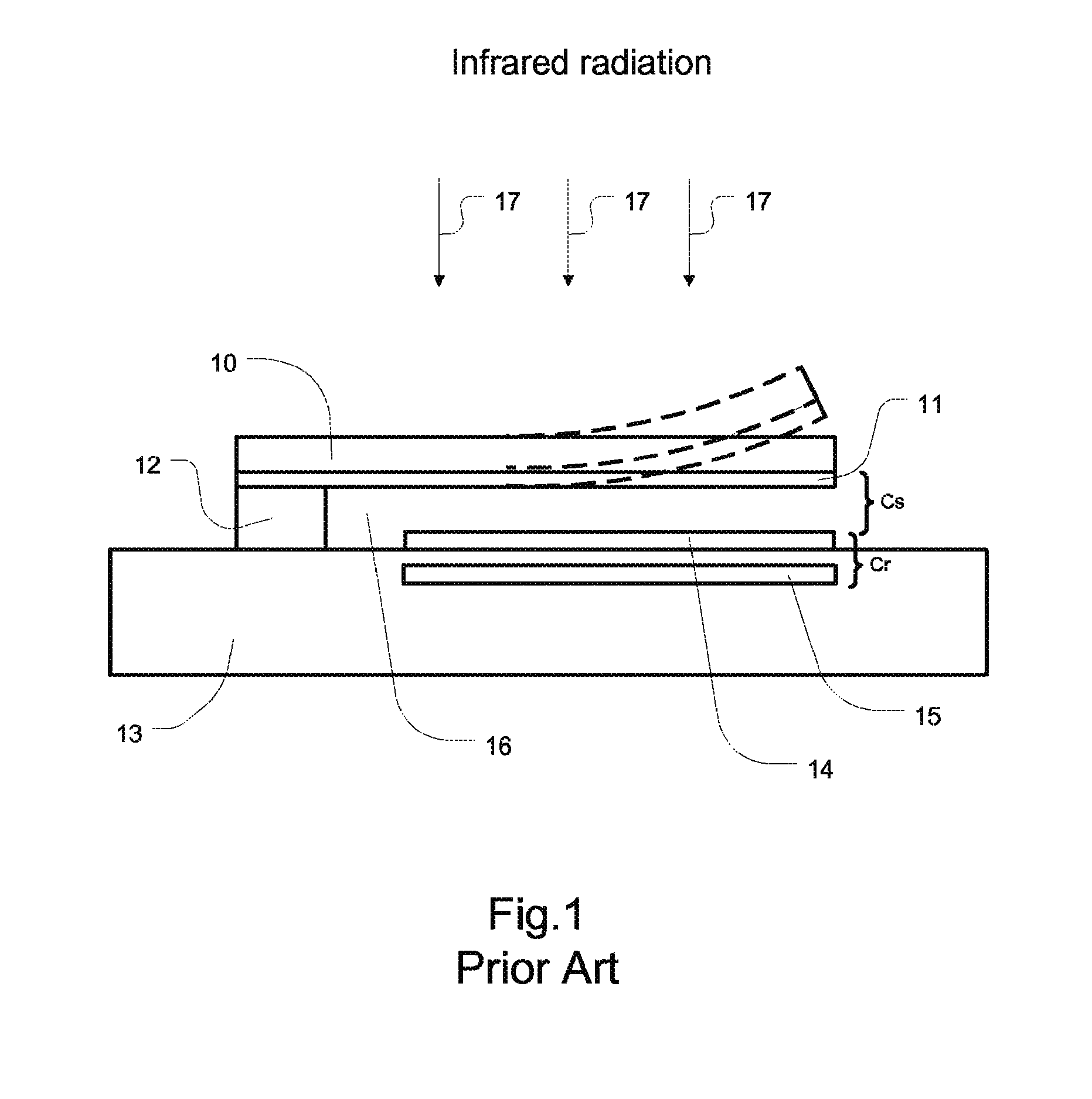
[0026]A prior art capacitive IR sensor is illustrated in FIG. 1. The prior art sensor consists of a bimaterial micro cantilever 10, 11, anchored 12 onto a substrate 13 The substrate can be made of silicon, quartz, or other ceramic materials known in the art. A bottom electrode 14 is made on the top surface of the substrate 13, and another buried electrode 15 is also made under electrode 14, and insulated from it using a dielectric layer. A gap 16 can be created using ordinary MEMS sacrificial layer and release method to allow the MEMS cantilever to move up and ...


PUM


Abstract

An IR imaging system comprising microelectromechanical systems (MEMS) differential capacitive infrared sensors within a sensor array formed on a monolithic integrated circuit substrate, or flip chip bonded onto a signal processing chip fabricated separately, to include, a bimaterial deflectable element anchored to the substrate, a surface electrode fabricated on a top surface of the substrate and positioned below the deflectable element, the surface electrode and the deflectable element separated by a gap to form a first variable capacitor, a sealing ring surrounding the deflectable element and the surface electrode, an infrared transparent sealing cap electrode coupled to the sealing ring to form a vacuum cavity around the deflectable element and the surface electrode, the deflectable element and the sealing cap electrode separated by a gap to form a second variable capacitor and a micro-lens fabricated on the sealing cap electrode to focus the infrared radiation onto the bimaterial deflectable element.

Description

CROSS-REFERENCE TO RELATED APPLICATIONS[0001]This application is a continuation-in-part of currently copending U.S. patent application Ser. No. 11 / 780,669 filed on Jul. 20, 2007, entitled, “Differential Capacitive Readout System and Method for Infrared Imaging”, which claims priority to U.S. Provisional Patent Application No. 60 / 807,891, filed on Jul. 20, 2006.STATEMENT OF GOVERNMENT INTEREST[0002]This invention was made with government support under NSF SBIR Grant No. DMI-0441165. The government has certain rights in the inventionFIELD OF INVENTION[0003]This invention relates to infrared imaging systems. More specifically, this invention relates to a differential capacitive readout system and method for an infrared imaging array with wafer level packaged cavity and micro machined on-chip micro-lenses.BACKGROUND OF THE INVENTION[0004]Infrared (IR) thermal imaging has a number of well-established industrial, commercial, and military applications, such as security, law enforcement sur...

Claims


Application Information

Patent Timeline
IPC IPC(8): G01J5/00G01J5/34H01L31/18
CPCG01J5/34H01L31/18G01J2005/0077G01J2005/345H01L27/14649B81B2201/0207H01L27/14618G01J5/40B81B7/0067B81B3/0081B81C1/00269
Inventor WANG, WEIDONGBUMGARNER, JOHN
Owner UNIV OF SOUTH FLORIDA
Learn More