Automatic weapon suppressor

a suppressor and automatic technology, applied in the direction of weapons, weapon components, etc., can solve the problems of slow blowdown, high pressure at the breech, and the typical baffle section of most suppressors does not allow rapid blowdown of weapons, so as to reduce heat transfer, reduce internal surface area, and reduce the effect of gas flow temperatur

Active Publication Date: 2016-05-24
UNITED STATES OF AMERICA THE AS REPRESENTED BY THE SEC OF THE ARMY
View PDF35 Cites 57 Cited by
  • Summary
  • Abstract
  • Description
  • Claims
  • Application Information

AI Technical Summary

Benefits of technology

[0032]Thermal management is addressed by subject invention by maintaining a low internal surface area to reduce heat transfer from the gas to the suppressor, and controls the sound through reduction and control of the pressure, not by reducing the temperature of the gas flow, as may be found in the prior art. The subject invention achieves this, in part, by its use of a more direct bypass gas flow pat

Problems solved by technology

While there are numerous suppressor designs which may accomplish this, an issue which remains is how to accomplish this while not affecting the overall performance of the weapon, especially high rate of fire weapons such as machine guns and carbines.
Typical baffle sections in most suppressors do not allow for rapid blowdown of the weapon due to supersonic flow choking effects at each baffle section.
This often cause slow blowdown, high pressure at the breech during weapon cycling, high pressure sections in the suppressor, which may require significant wall thickness and added weight, and higher temperatures in the high pressure sections.
Suppressors, when added to a weapon typically reduce the blow down rate and increase the back pressure in the weapon.
This high pressure can cause case ejection problems, propellant fouling, propellant gases in the operators face and other problems.
In addition, a reduced blowdown rate can cause changes in weapon powering of either piston driven or gas tube driven weapons.
This can cause increased bolt velocities beyond weapon design limits and potentially damage weapon parts unless pressures can be reduced at the gas port by some means.
The critical issue with regards to blowdown management of weapon suppressors is to increase the blowdown rate while not increasing the blast overpressure levels significantly.
Weapon flash may be caused by unburnt propellant at high temperatures exiting the suppressor where it mixes with the outside air and ignites.
Thermal management of weapon suppressors is also critical because they tend to absorb large amounts of heat when placed on a weapon.
While some suppressors may reduce the pressure of the exiting flow by acting as a heat sink to absorb thermal energy, thereby cooling the gas and reducing its volume, this ef

Method used


Image

  • Automatic weapon suppressor
  • Automatic weapon suppressor
  • Automatic weapon suppressor

Examples


Embodiment Construction

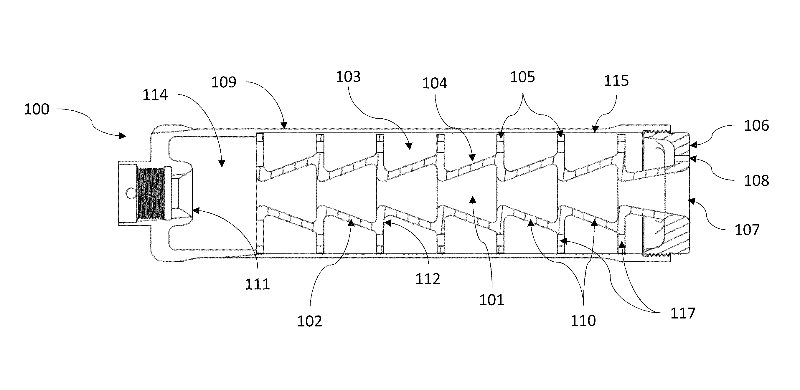
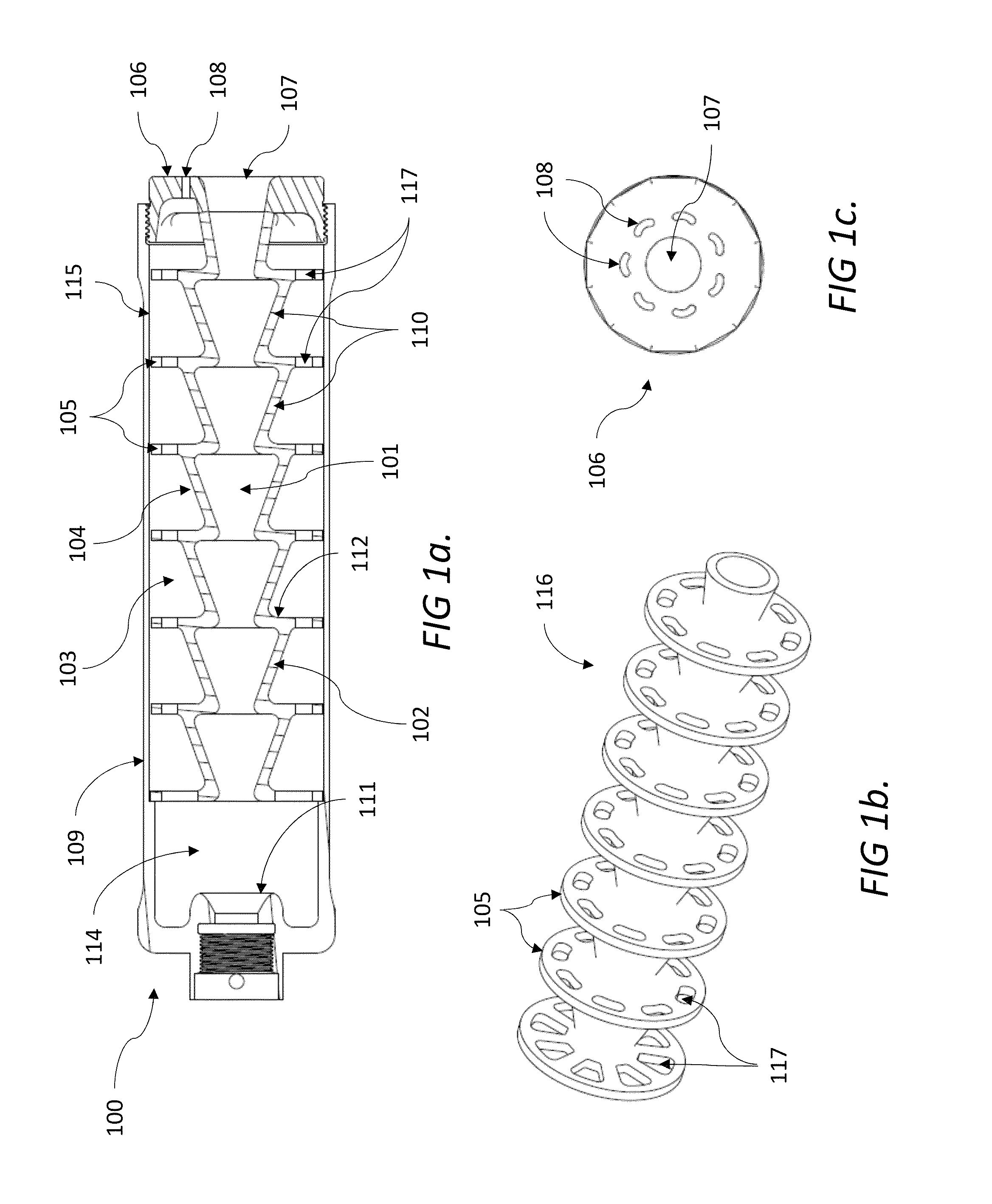
[0040]Note that the terms ‘central chamber’, ‘core chamber’ and ‘central core chamber’ are used interchangeably.

[0041]As shown in FIG. 1a, suppressor [100] for automatic and semi-automatic weapons for rapid bleed down of weapon pressure, according to an embodiment of the subject invention, may include: a baffled central chamber [101], configured along the bore axis, formed by a series unported K-baffles [102]; a baffled bypass chamber [103], disposed surrounding the central chamber [101], providing a high flow area, forward directed flow path, wherein inner surface [104] of said bypass chamber [103] is substantially defined by the exterior shape of the unported K-baffle system [102] and which may further include a plurality of baffles [105, 113] such as annular rings or ported [117] partitions [105]. Propellant gasses may expand into the bypass chamber [103] before the central chamber [101] begins, and thereafter there is no fluid communication between the central [101] and bypass c...


PUM


Abstract

A suppressor for rapid fire weapons designed to rapidly bleed down the weapon pressure and thereby minimizing gas blowback to the operator and to the weapon's gas operating system; while also creating a shear gas flow about the exiting bullet's gas flow to mask the flash thereof. The suppressor is configured within a generally cylindrical housing, having: (1) a central core of unported K-baffles located about a central bulletway; (2) a bypass located between the cylindrical housing and the unported K-baffled central core—providing a generally forward subsonic high gas flow area to an endcap closing the cylindrical housing; (3) said endcap having a series of vent ports for the bypass, which also create a shear flow about the centrally exiting bullet; and (4) wherein the series of unported K-baffles are spaced away from the weapon's bore end to allow the propellant gasses to expand into the bypass.

Description

CROSS-REFERENCE TO RELATED APPLICATIONS[0001]This application claims the benefit of U.S. Provisional Application No. 61 / 985,643 filed on Apr. 29, 2014, which is incorporated herein by reference.STATEMENT OF GOVERNMENT RIGHTS[0002]The inventions described herein may be manufactured, used and licensed by or for the U.S. Government for U.S. Government.BACKGROUND[0003]1. Field of the Invention[0004]The present invention relates to a weapon suppressor system capable of minimizing the gas backflow to the operator and to the weapon's operating system, as well as, minimizing the weapon flash—the system comprising a unique central baffle and bypass system.[0005]2. Description of the Related Art[0006]Firearm suppressors are designed to attach to the muzzle of a weapon and reduce the noise and flash generated by said weapon when it is fired. While there are numerous suppressor designs which may accomplish this, an issue which remains is how to accomplish this while not affecting the overall pe...

Claims


Application Information

Patent Timeline
IPC IPC(8): F41A21/00F41A21/30
CPCF41A21/30
Inventor CLER, DANIEL L.
Owner UNITED STATES OF AMERICA THE AS REPRESENTED BY THE SEC OF THE ARMY
Why Eureka
Try Eureka