
Generating optical pulses via a soliton state of an optical microresonator

a soliton state and microresonator technology, applied in optics, laser details, instruments, etc., can solve the problems of difficult to achieve the goal, the inability to generate conventional frequency combs, and the inability to maintain the temporal and phase properties of optical pulses, so as to improve the coupling efficiency of coupling cw laser light into the optical microresonator, the effect of compact and stable structure of light pulse sour

Active Publication Date: 2016-05-24
ECOLE POLYTECHNIQUE FEDERALE DE LAUSANNE (EPFL)
View PDF6 Cites 7 Cited by
  • Summary
  • Abstract
  • Description
  • Claims
  • Application Information

AI Technical Summary

Benefits of technology

This patent describes a new method for generating high-quality optical pulses using a microresonator and a cw laser. The invention allows for the wavelength and intensity of the laser to be controlled simultaneously, which can affect the resonator's temperature, Kerr-nonlinear resonance shift, and coupling efficiency. Additionally, a strain tuning device can change the mechanical strain and geometrical extend of the optical microresonator, and changing the temperature can affect the optical microresonator's properties. The light pulse source includes input and output waveguides that allow for efficient coupling of laser light into and out of the microresonator, which results in improved temporal and phase properties of the optical pulses. The invention also has a laser pump stabilizing mechanism that ensures a stable light pulse source duration over practical time ranges.

Problems solved by technology

Nevertheless, the conventional generation of frequency combs still suffers from the following substantial problem.
However, a mode-locking mechanism has not been disclosed in EP 1 988 425 A1, and the frequency combs conventionally created with practical resonators typically do not have a pulse shape.
Moreover, mode-locking would provide a way to achieve low-noise frequency comb spectra, with little line-to-line power variation and without spectral gaps—a goal difficult to reach in systems with mode-spacings below 100 GHz, where multiple, inconsistent subcombs may form.
Introducing a saturable absorber or an equivalent optical element into the laser cavity, easily possible in conventional laser systems, would impair the optical quality factor Q of the microresonator.
Approaches with other mode-locking mechanisms based on self-focusing or small saturable components of material absorption were not successful.
This soliton formation could lead to mode-locking.
However, to date no definitive proof nor practical mechanism of optical mode locking has been identified.

Method used


Image

  • Generating optical pulses via a soliton state of an optical microresonator
  • Generating optical pulses via a soliton state of an optical microresonator
  • Generating optical pulses via a soliton state of an optical microresonator

Examples


Embodiment Construction

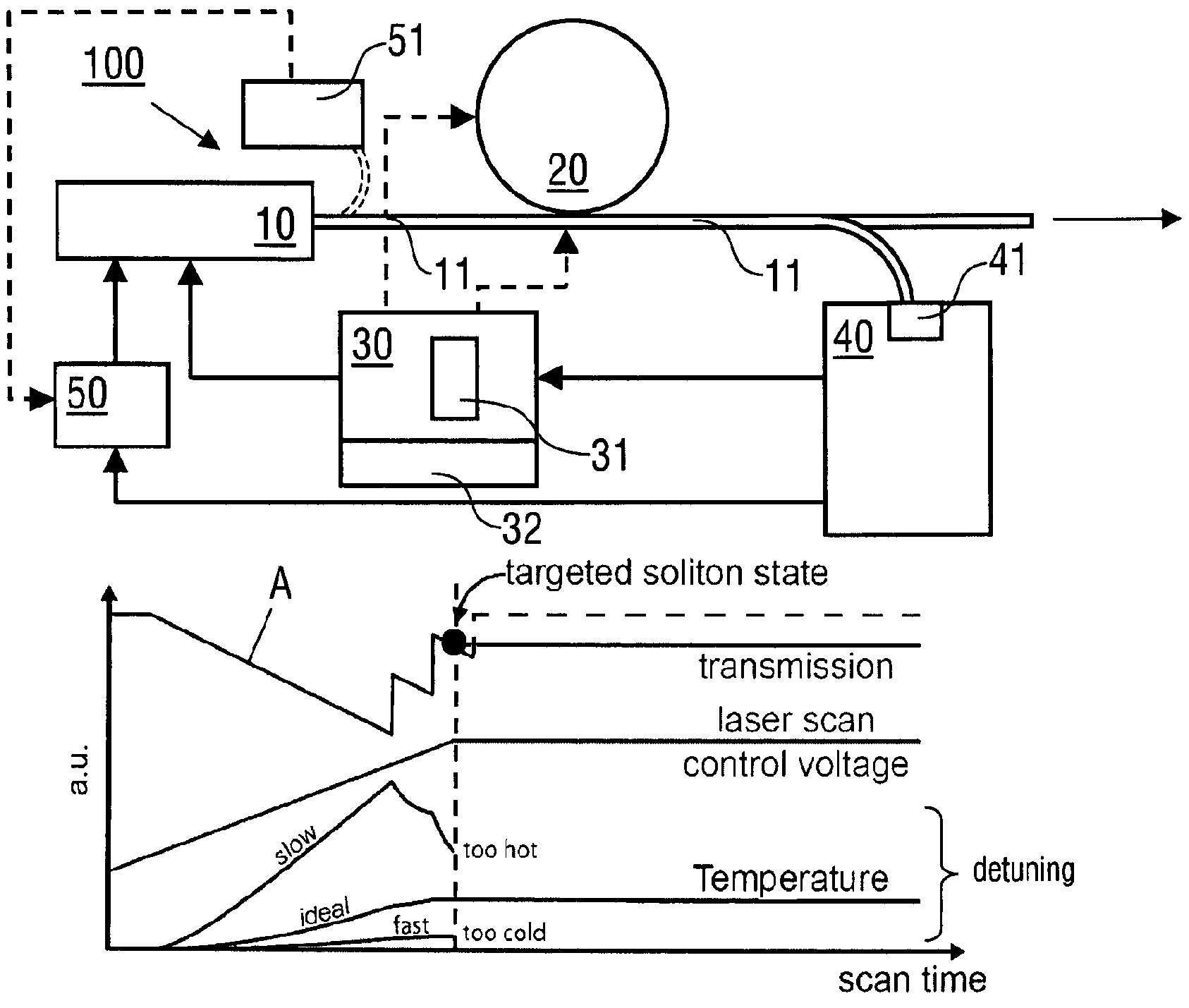
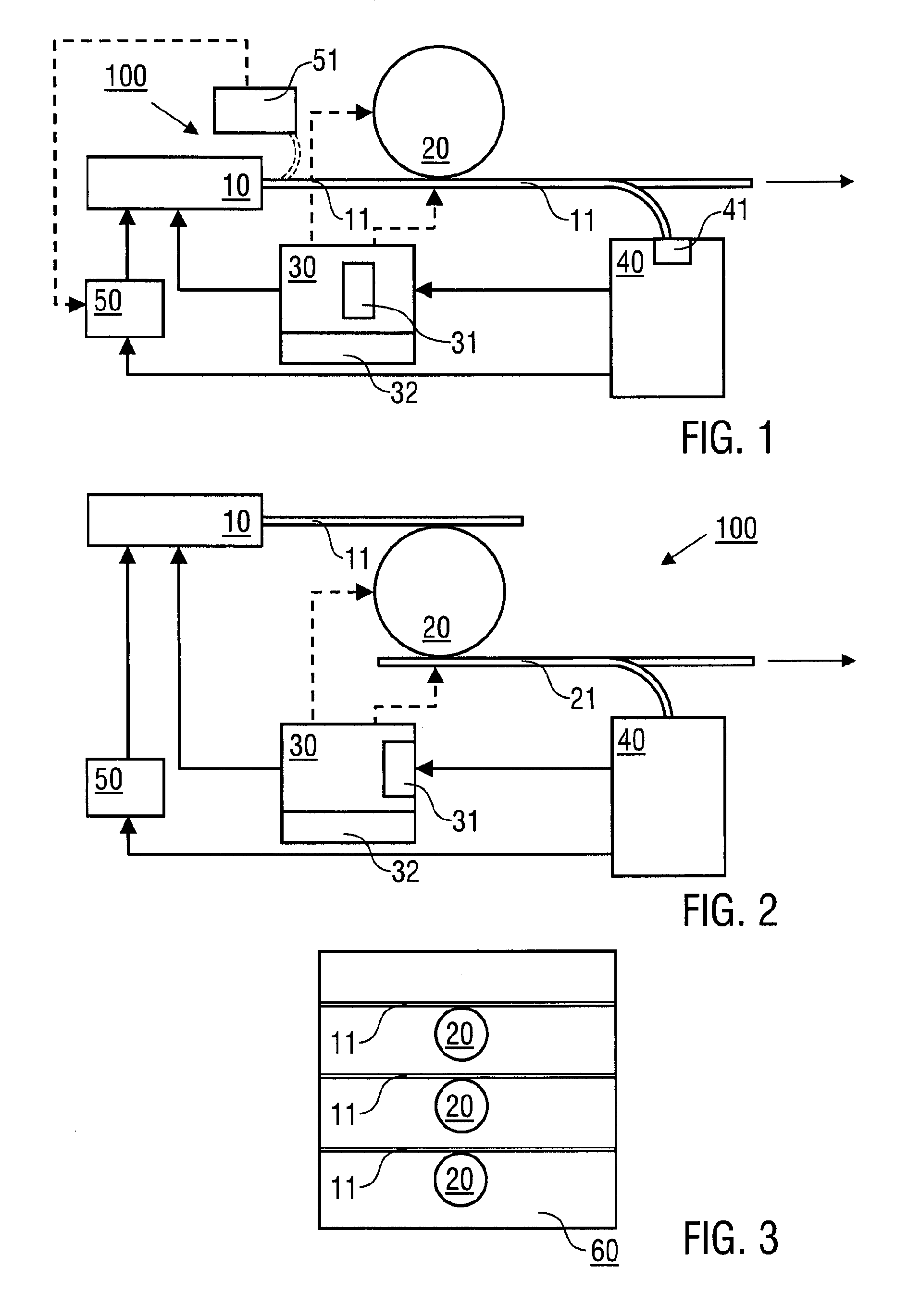
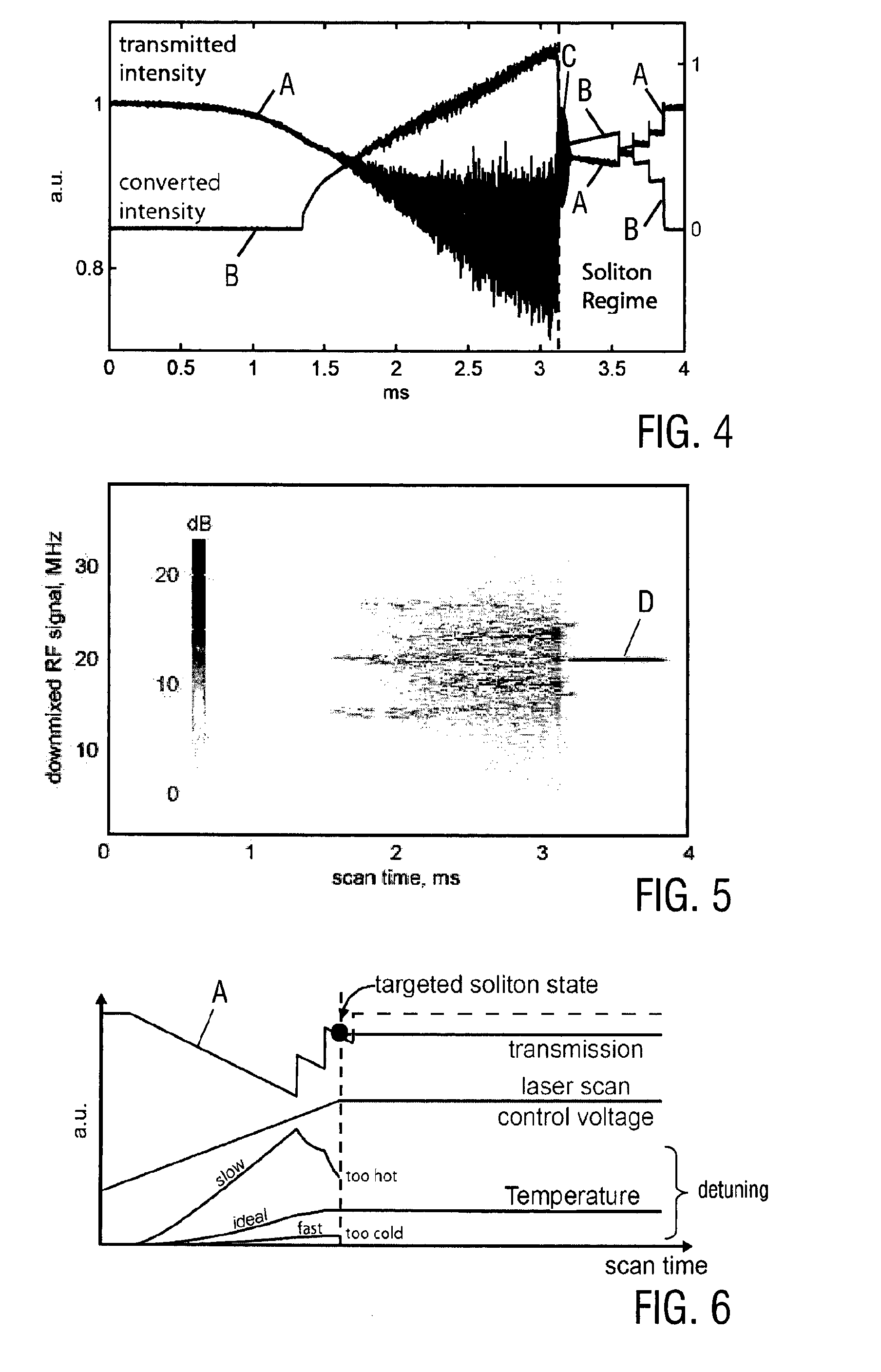
[0037]Preferred embodiments of the invention are described in the following with particular reference to the structure of the inventive light pulse source and in particular the features of a tuning device, which is used for achieving the soliton state of the optical microresonator. Exemplary reference is made to the use of a WGM microresonator made of an MgF2 crystal. It is emphasized that the invention is not restricted to this particular type of an optical microresonator, but rather possible with other resonators being made of e.g. CaF2, BaF2, SiN, AlN, SiO or Si. Furthermore, exemplary reference is made to the use of a tuning device, which is adapted for wavelength and / or intensity tuning the light pulse source. The invention is not restricted to this exemplary tuning mechanism, but rather possible with other tuning mechanisms, which are capable of creating and maintaining a predetermined relative detuning between a cw laser and the optical microresonator, like e.g. coupling tuni...


PUM

PropertyMeasurementUnit
mode-field diameteraaaaaaaaaa
line widthaaaaaaaaaa
diameteraaaaaaaaaa

Abstract

A light pulse source (100), being adapted for generating repetitive optical pulses, comprises a continuous wave (cw) laser (10) being arranged for providing cw laser light, an optical microresonator (20) being made of a resonator material, which has a third order (Kerr) nonlinearity and an anomalous resonator dispersion, wherein the cw laser (10) is arranged for coupling the cw laser light into the optical microresonator (20), which, at a predetermined relative detuning of the cw laser (10) and the optical microresonator (20), is capable of including a light field in a soliton state, wherein soliton shaped pulses can be coupled out of the optical microresonator (20) for providing the repetitive optical pulses, and a tuning device (30) being arranged for creating and maintaining the predetermined relative detuning of the cw laser (10) and the optical microresonator (20) based on a tuning time profile being selected in dependency on a thermal time constant of the optical microresonator (20) such that the soliton state is achieved in a thermal equilibrium state of the optical microresonator (20). Furthermore, a method of generating repetitive optical pulses is described based on soliton shaped pulses coupled out of an optical microresonator (20) is described.

Description

FIELD OF THE INVENTION[0001]The present invention relates to a light pulse source, which is adapted for generating repetitive optical pulses using an optical microresonator which is made of a resonator material with a third order (Kerr) nonlinearity and an anomalous resonator dispersion. Furthermore, the present invention relates to a method of generating repetitive optical pulses with an optical microresonator. Applications of the invention are available e. g. in metrology, in particular with compact optical clocks, telecommunications, optical information processing, information transmission, astronomy, medical diagnostics and treatment and spectroscopy.BACKGROUND OF THE INVENTION[0002]The discovery of passive mode-locking via saturable absorbers has led to optical femto-second pulses with applications ranging from eye-surgery to the analysis of chemical reactions on ultra-short timescales. In the frequency domain, a train of such optical pulses corresponds to a frequency comb (equ...

Claims


Application Information

Patent Timeline
Patent Type & Authority Patents(United States)
IPC IPC(8): G02F1/035G02F1/355G02F1/35G02F1/365H01S3/00G02B6/293
CPCG02F1/3513G02B6/29338G02F1/3536G02F1/3551G02F1/365H01S3/0092G02F2203/15G02F2203/17G02F2203/56G02F2201/58
Inventor HERR, TOBIASGORODETSKY, MICHAEL L.KIPPENBERG, TOBIAS
Owner ECOLE POLYTECHNIQUE FEDERALE DE LAUSANNE (EPFL)
Learn More