Gain-boosted N-path bandpass filter

a bandpass filter and gain-boosting technology, applied in the field of bandpass filters, can solve the problems of unsolved area and power and area costs, and achieve the effect of small capacitors

Active Publication Date: 2016-06-21
UNIVERSITY OF MACAU
View PDF5 Cites 11 Cited by
  • Summary
  • Abstract
  • Description
  • Claims
  • Application Information

AI Technical Summary

Benefits of technology

[0015]3. The present invention have much smaller capacitors

Problems solved by technology

However, in the absence of RF gain, a considerable amount of power is entailed for the local oscillator (LO) to drive up the mixers that must be essentially large (i.e., small on-resistance, Rsw) for an affordable noise figure (NF<5 dB).
Repeatedly adopting such filters at different RF nodes

Method used


Image

  • Gain-boosted N-path bandpass filter
  • Gain-boosted N-path bandpass filter
  • Gain-boosted N-path bandpass filter

Examples


Embodiment Construction

I. GB-BPF using an Ideal RLC Model

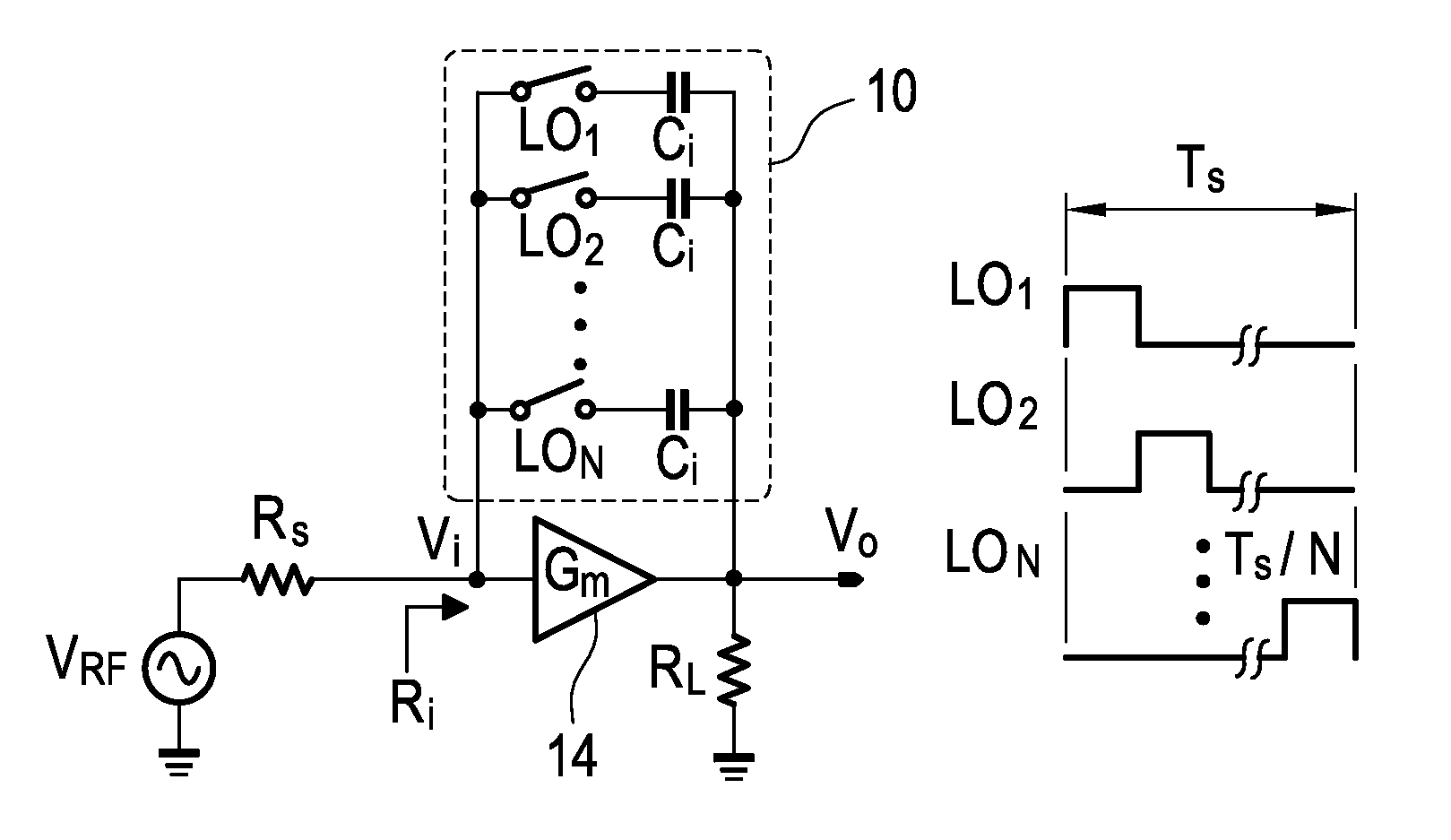
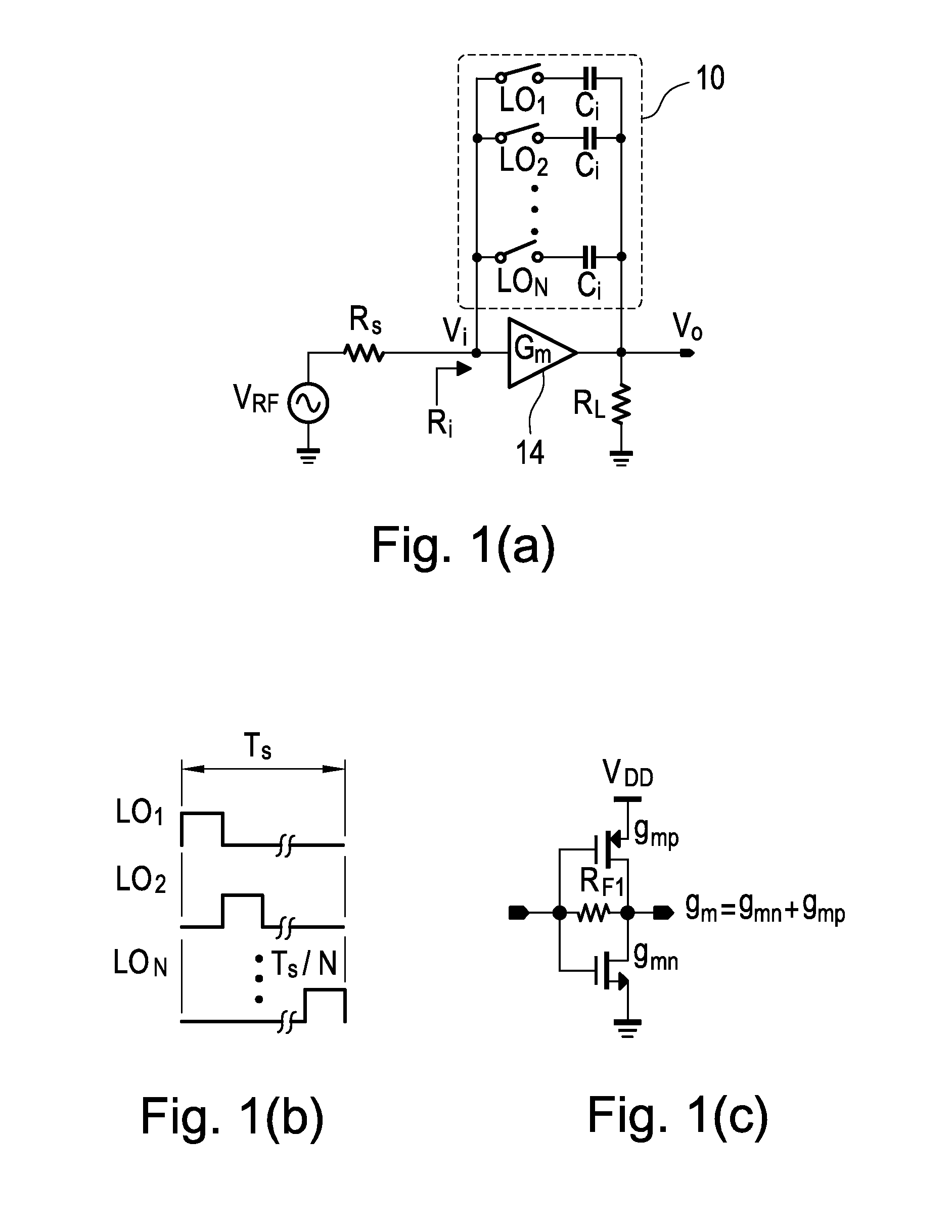
[0050]The proposed GB-BPF is depicted in FIG. 1(a). It features a transconductance amplifier (Gm) 14 in the forward path, and an N-path SC branch 10 driven by an N-phase non-overlapped LO in the feedback path. When one of the switches is ON, an in-phase RF voltage VRF will appear on the top plate of capacitor Ci, and induces an amplified anti-phase voltage into its bottom plate. When the switch is OFF, the amplified version of VRF will be stored in Ci. There are three observations: 1) similar to the well-known capacitor-multiplying technique (i.e., Miller effect) in amplifiers, the effective capacitance of Ci at the input node Vi will be boosted by the loop gain created by Gm 14, while it is still Ci at the output node Vo. This feature, to be described later, reduces the required Ci when comparing it with the traditional passive N-path filter. 2) For the in-band signal, the voltages sampled at all Ci are in-phase summed at Vi and Vo after a complete...


PUM


Abstract

The present invention discloses a gain-boosted N-path SC bandpass filter (GB-BPF) with a number of sought features. It is based on a transconductance amplifier (Gm) with an N-path SC branch as its feedback network, offering 1) double RF filtering at the input and output of the Gm in one step; 2) customized passband gain and bandwidth with input-impedance match, and 3) reduced physical capacitance thanks to the loop gain offered by Gm. All have been examined using a RLC model of the SC branch before applying the linear periodically time-variant (LPTV) analysis to derive the R, L and C expressions and analytically study the harmonic selectivity, harmonic folding and noise. The latter reveals that: 1) the noise due to the switches is notched at the output, allowing smaller switches to save the LO power; and 2) the noises due to the source resistance and Gm are narrowband at the output, reducing the folded noise during harmonic mixing.

Description

BACKGROUND OF THE INVENTION[0001]1. Field of the Invention[0002]The present invention relates to a bandpass filter, especially relates to a gain-boosted N-path switched-capacitor (SC) bandpass filter.[0003]2. Description of the Prior Art[0004]The demand of highly-integrated multi-band transceivers has driven the development of blocker-tolerant software-defined radios that can avoid the cost (and loss) of the baluns and SAW filters. The passive-mixer-first receivers achieve a high out-of-band (OB) linearity (IIP3=+25 dBm) by eliminating the forefront low-noise amplifier (LNA). However, in the absence of RF gain, a considerable amount of power is entailed for the local oscillator (LO) to drive up the mixers that must be essentially large (i.e., small on-resistance, Rsw) for an affordable noise figure (NF<5 dB). The noise-cancelling receiver breaks such a NF-linearity tradeoff, by noise-cancelling the main path via a high-gain auxiliary path, resulting in better NF (1.9 dB). However...

Claims


Application Information

Patent Timeline
IPC IPC(8): H03H19/00H03H11/04H03H11/12
CPCH03H11/0427H03H19/004H03H11/1291H03H19/002H03H2210/025H03B5/1237H03B5/1246H03B2202/06H03H11/0472H03H2011/0483H03F1/0205H03F3/19H03F3/45076H03F2200/294H03F2200/451H04B1/1638H04B1/16
Inventor MAK, PUI-INLIN, ZHICHENGMARTINS, RUI PAULO DA SILVA
Owner UNIVERSITY OF MACAU
Why Eureka
Try Eureka