Method of manufacturing solid solution perforator patches and uses thereof

a technology of solid solution and perforator, which is applied in the field of manufacturing solid solution perforator patches, can solve the problems of affecting the ability of microneedle array master microneedle to be easily damaged, difficult to manufacture, and difficult to ensure drug penetration

Active Publication Date: 2016-07-05
THERAJECT INC.
View PDF165 Cites 7 Cited by
  • Summary
  • Abstract
  • Description
  • Claims
  • Application Information

AI Technical Summary

Benefits of technology

[0007]The present invention overcomes these problems and provides inexpensive and uncomplicated methods for manufacturing SSP drug delivery systems including dissolvable microneedles. In particular, the invention provides a method for constructing positive microneedle master molds made from an array of various types of fine needles.
[0008]The microneedles for use in the present invention are made by making a mold from a metal, polymer, or glass (or other extendable) material wire. For making a positive master mold from an alignment needle, the individual needles for the positive master are made by, for example, grinding a wire end or pulling a wire and then sharpening. Other suitable methods for making sharp needles are known and will find use herein. The needles may have various shapes, for example, round in cross-section or square in cross-section. The individual needles from wires are integrated or arranged into the master structure relatively quickly and with much less expense than making a negative mold which is used to cast the final dissolving microneedles.
[0011]Another method for constructing a positive master mold is to cast microneedles from a negative mold fabricated by the MEMS fabrication method or the CNC precision machining method such as by drilling or grinding. From the master microneedle array structure, a mold, called a “negative mold” herein, can be made and used for fabricating dissolvable SSPs. The dissolvable system includes a solid matrix of dissolvable (including meltable) material that optionally holds one or more selected drugs and is formed into one or more perforators from the negative mold. The matrix can be composed of fast-dissolving and / or swelling materials. The solid solution can be a homogeneous, non-homogeneous, suspension solution with a different drug loading phase. In order to make the dissolving SSPs, a positive master prototype is first manufactured with the methods described above. A negative mold of silicone or curable materials is then fabricated from the positive master. In particular, the secondary silicone negative mold fabrication allows cost-effective mass production and utilizes the inherent properties of silicone materials, such as surface tension, flexibility, gas-permeation, and the like. In another embodiment, the silicone negative mold is not separated from the microneedle array until the microneedle array is used. In this embodiment, the silicone mold is used as packaging material to keep the microneedle array intact because the silicone material is reasonably inexpensive.
[0012]In another embodiment of the negative mold, the microneedle cavity in the negative mold has an open end at the cavity bottom corner to easily fill the cavity with gel by applying a vacuum through the hole or even by pressing gel into the cavity.
[0014]A cartridge can be used in the injection device as described in U.S. Pat. Nos. 6,945,952, 7,182,747 and 7,211,062, incorporated herein by reference in their entireties. The drug-microneedle array patch is attached in the center of the cartridge to bring the microneedle tips into contact with the skin of the injection target. The cartridge is mounted to the end of the injector, such as by rotation-locking, push-fitting, detachable glue, by magnetic attachment, or by using a temporary locking mechanism of the cartridge at the end of the injector. The penetrating depth of the microneedles can be made consistent by hitting the microneedles in the cartridge by the applicator. Typically, the cartridge is flat and thin, preferably not thicker than about 10 mm. The exterior of the cartridge can be in any of various shapes and sizes. The cartridge can be made of moldable plastic. The cartridge may be designed for one-time use and can be disposable. The cartridge can be attached on the injector piston to be moved with the piston to the skin. In one embodiment, the microneedle array is placed close to the target skin instead of onto the piston of the injector. This design is simple for use and mass-production without losing the efficiency. An alternative method for applying the patch is to insert the patch with the thumb or a finger and the insertion force and duration can be controlled by using a pressure sensor film or inserting device.
[0015]Another method for penetrating effectively into the skin is to increase the mechanical strength of the microneedles by a formulating and post-drying process of the microneedle. In particular, by adding a mono- or di-saccharide to the matrix polymer, carboxymethyl cellulose, the mechanical strength can be improved. In addition, use of a post-drying process (or removing additional water content from the microneedle matrix) after separating from the mold improves the mechanical strength of the microneedle.

Problems solved by technology

However, there are barriers involved in providing sufficient drug penetration across the skin.
Unfortunately, silicon needles are not dissolvable in the skin, can break during use and stay in the skin tissue, producing considerable irritation and even infection.
However, MEMS fabrication for the master microneedle array can be expensive and complicated.
Moreover, the polymeric microneedles may require drug loading or drug coating, rendering the casting methods unsuitable for mass production.

Method used


Image

  • Method of manufacturing solid solution perforator patches and uses thereof
  • Method of manufacturing solid solution perforator patches and uses thereof
  • Method of manufacturing solid solution perforator patches and uses thereof

Examples


example 1

Fabrication Positive Master and SSPS from Silicone Mold

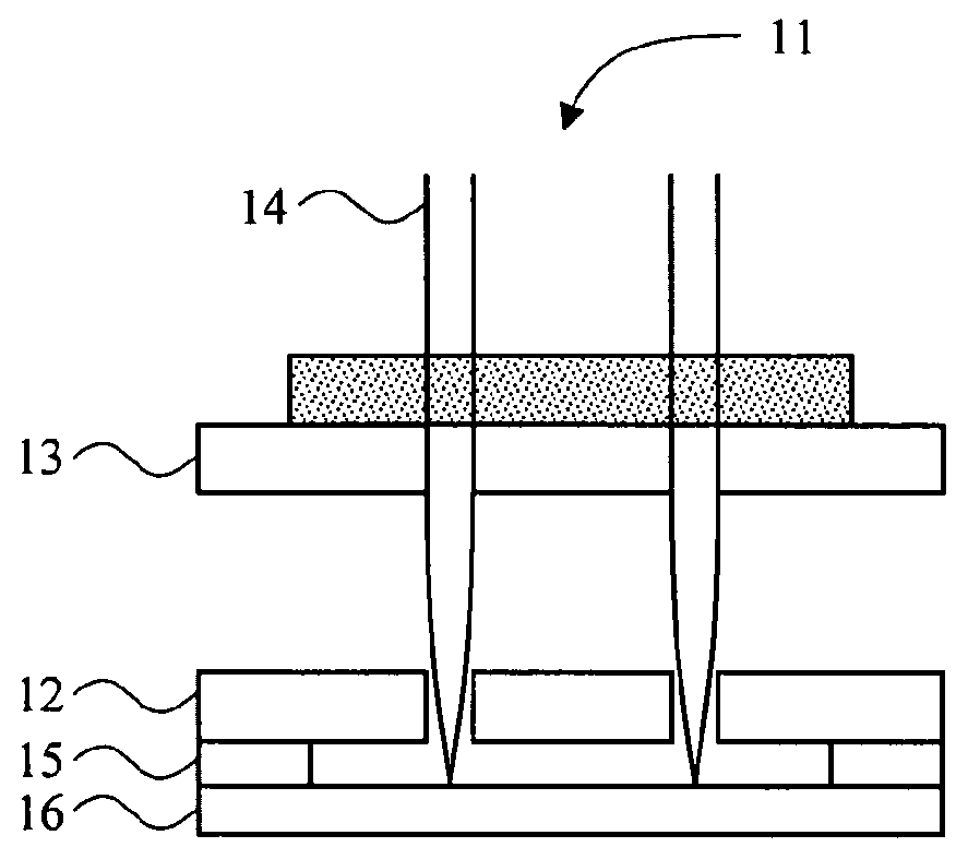
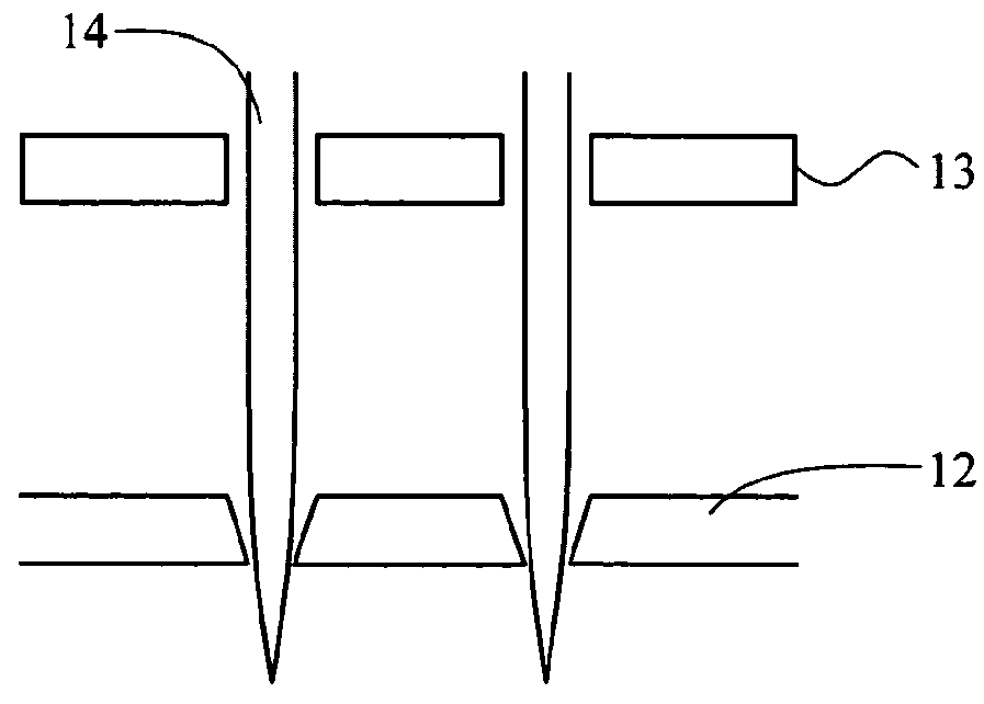
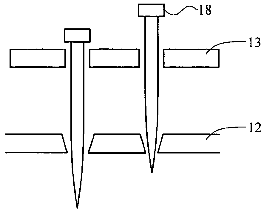
[0080]Holes were made in glass as shown in FIG. 1D by chemical etching through holes on a photoresist film patterned by photolithography and acupuncture needles were aligned through the holes 114. The tip of the needles through the holes are depicted. PDMS was poured on this side and cured overnight. 8% sodium methyl cellulose hydrogel was poured on this silicone mold and centrifuged at 3,000 rpm for 5 minutes. After centrifuging, the hydrogel was dried for one day and separated from the mold. FIG. 5 is the image of dissolvable microneedle made of cellulose. Another micromold from CNC profile forming grinding techniques is depicted in FIG. 1F.

example 2

Compression Break Force and Dissolution Time with Various Compositions

[0081]Compression testing was done with a force gauge (NexyGen DF series) and the conical compression force applied until the microneedles broke was measured. The test samples were prepared with various sugar derivatives and sodium carboxy methyl cellulose (SCMC). The 8% SCMC was mixed with DI water. The dissolution time for to fully dissolve the SCMC in 10 ml of DI water at 300 rpm was measured. Since the sugar derivatives were added to the fixed 8% SCMC hydrogel, the results were normalized over weight. Results are shown in Table 1.

[0082]

TABLE 1Formulation compositionDissolution timeConical compression(SCMC:Lactose)(min)force (N)SCMC = 10010.81 ± 0.0311.27 ± 0.75SCMC:Trehalose = 91:910.73 ± 0.6317.13 ± 1.95SCMC:MaltoDextrin = 91:910.25 ± 0.3915.23 ± 5.24SCMC:Sucrose = 91:911.00 ± 1.0117.77 ± 1.08SCMC:PVP = 91:911.21 ± 0.9419.50 ± 6.66SCMC:Glucose = 91:910.59 ± 1.8810.61 ± 0.23SCMC:Mannitol = 91:911.07 ± 0.8616.1...

example 3

Mechanical Properties with Different Lactose Compositions

[0083]Compression and dissolution tests were done on various compositions of lactose. As lactose was added, the test article dissolved faster and compression force increased. See, Table 2.

[0084]

TABLE 2Formulation compositionConical compression(SCMC:Lactose)Dissolution time (min)force (N)SCMC:Lactose = 100:010.81 ± 0.03 11.27 ± 0.75SCMC:Lactose = 91:910.55 ± 0.24 18.03 ± 2.50SCMC:Lactose = 83:178.68 ± 0.1323.25 ± 0.21SCMC:Lactose = 77:237.87 ± 0.4521.87 ± 3.62SCMC:Lactose = 71:297.03 ± 0.1429.93 ± 6.94SCMC:Lactose = 67:337.02 ± 0.61 23.90 ± 13.75SCMC:Lactose = 62:387.79 ± 0.0539.57 ± 2.19SCMC:Lactose = 44:566.57 ± 0.0324.47 ± 1.11SCMC:Lactose = 29:714.58 ± 0.7545.56 ± 4.29SCMC:Lactose = 21:793.91 ± 0.6575.25 ± 2.20


PUM

PropertyMeasurementUnit
diameteraaaaaaaaaa
lengthaaaaaaaaaa
lengthaaaaaaaaaa

Abstract

Methods for fabricating and manufacturing solid solution perforators (SSPs) using sharp metal or glass needles and / or subsequent molding and use are described. The methods entail making microneedles by various precision machining techniques and micromold structures from curable materials. Various designs of patch, cartridge and applicator are described. Also described are methods for adjusting the microneedle mechanical strength using formulation and / or post-drying processes.

Description

CROSS-REFERENCE TO RELATED APPLICATIONS[0001]This application is a National Stage Patent Application of International Patent Application No. PCT / US2009 / 003145 (filed on May 21, 2009) under 35 U.S.C. §371, which claims priority to U.S. Provisional Application No. 61 / 128,405 (filed on May 21, 2008), which are all hereby incorporated by reference in their entirety.TECHNICAL FIELD[0002]The present invention relates generally to a method for fabricating and manufacturing solid solution perforators (SSPs) such as dissolving microneedles using sharp metal or glass needles or precision machining and / or subsequent molding. More particularly, the invention relates to a method of creating micromold structures made of curable materials, from fine needle array alignments, and uses thereof. Additionally, the invention relates to methods for increasing mechanical strength of microneedles, designing flexible microneedle patches, and patch injection / insertion and uses thereof.BACKGROUND OF THE INVEN...

Claims


Application Information

Patent Timeline
Patent Type & Authority Patents(United States)
IPC IPC(8): A61M37/00B29C33/38B29C33/30A61B17/20B29C33/00A61B17/00
CPCB29C33/3885A61B17/205A61M37/0015B29C33/0027B29C33/0033B29C33/308B29C33/3878A61B2017/00345A61B2017/00761A61M2037/0023A61M2037/0046A61M2037/0053A61M2037/0061
Inventor OH, SEA-JINKWON, SUNG-YUN
Owner THERAJECT INC.
Why Eureka
Try Eureka