Anode and battery

a technology applied in the field of anode and battery, can solve the problems of low cycle characteristics, low capacity of lithium secondary batteries, and low current collection properties, and achieve the effect of preventing an increase in impedance in batteries

Active Publication Date: 2016-08-23
MURATA MFG CO LTD
View PDF14 Cites 2 Cited by
  • Summary
  • Abstract
  • Description
  • Claims
  • Application Information

AI Technical Summary

Benefits of technology

[0010]In view of the foregoing, it is an object of the invention to provide an anode capable of preventing an increase in impedance in a battery and variations in characteristics, and a battery using the anode.
[0013]In the anode according to the invention, a coating including lithium carbonate is included on at least a part of a surface of the anode active material layer, so the amount of lithium oxide or lithium hydroxide formed on the surface of the anode active material layer can be reduced, and when the anode is applied to the battery according to the invention, an increase in impedance in the battery can be prevented. Moreover, the anode is less subject to an influence by a difference in a handling environment or storage conditions, so variations in impedance can be prevented.
[0014]Specifically, when lithium is inserted into the anode active material layer, in the early stages of cycles, the consumption of lithium by a reaction with an electrolyte solution can be prevented, and even if lithium is consumed, lithium can be refilled, and degradation in the early stages can be prevented. Moreover, a stress on the anode current collector due to expansion and shrinkage of the anode active material layer according to charge and discharge can be reduced. Further, when electrically active lithium remains in the anode after discharge, an increase in the potential of the anode in the late stages of discharge can be prevented, and degradation according to an increase in the potential of the anode can be prevented. Therefore, battery characteristics such as cycle characteristics can be improved.
[0015]Moreover, when lithium is inserted through depositing lithium metal by a vapor-phase deposition method, lithium can be inserted in a process of depositing lithium metal, so handling can be easier. Further, the amount of lithium to be inserted can be easily controlled, and lithium can be uniformly inserted in a large area. Moreover, in the case where the anode active material layer is formed by a vapor-phase deposition method, a step of forming a film of the anode active material and a step of inserting lithium can be successively carried out, so manufacturing steps can be simplified.
[0016]In addition, when the coating including lithium carbonate is formed through inserting lithium into the anode active material layer, and then bringing the anode active material layer into contact with carbon dioxide, lithium is diffused over the anode active material layer, and alloyed with the anode active material layer, so compared to lithium metal, the surface of the anode active material layer is less active, and the thickness and variations of the coating can be reduced. Therefore, an increase in impedance in the battery and variations in characteristics can be prevented.
[0017]Further, when the anode active material layer includes at least one kind selected from the group consisting of simple substances, alloys and compounds of silicon, germanium and tin, a higher capacity can be obtained, and a loss in the capacity due to insertion of lithium in advance can be reduced. Further, when lithium is inserted, dangling bonds existing in the anode active material layer or impurities such as hydrogen and oxygen can be reduced, so battery characteristics such as cycle characteristics can be improved.

Problems solved by technology

However, the battery capacity of a currently typical lithium secondary battery which uses lithium cobalt oxide as a cathode and graphite as an anode has reached a point of saturation, so it is extremely difficult to substantially increase the capacity of the lithium secondary battery.
However, when charge and discharge are repeated, the anode with a high capacity is broken into small pieces due to severe expansion and shrinkage of an active material, thereby a current collecting property declines, or the decomposition of an electrolyte solution is accelerated due to an increase in a surface area, thereby cycle characteristics are extremely poor.
However, even in the anode, the cycle characteristics are not sufficient because of a nonreversible reaction of an active material according to charge and discharge.
Moreover, as in the case of a conventional anode with a high capacity, the reactivity with an electrolyte is still high, so the capacity largely declines due to a reaction with the electrolyte according to charge and discharge especially in the early stages of cycles.
Further, in the anode with a high capacity, an anode potential is largely increased according to extraction of lithium especially in the late stages of discharge, which is one of factors causing a decline in characteristics.
The coating causes an increase in impedance in the battery and degradation in battery characteristics.

Method used


Image

  • Anode and battery
  • Anode and battery
  • Anode and battery

Examples


examples

[0074]Examples of the invention will be described in detail below referring to FIGS. 1 through 4. In the following examples, like components are donated by like numerals as of the above embodiment.

examples 1-1 through 1-5

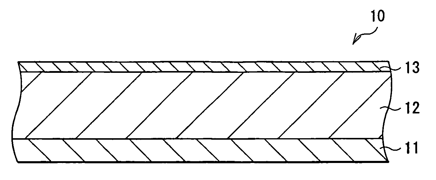
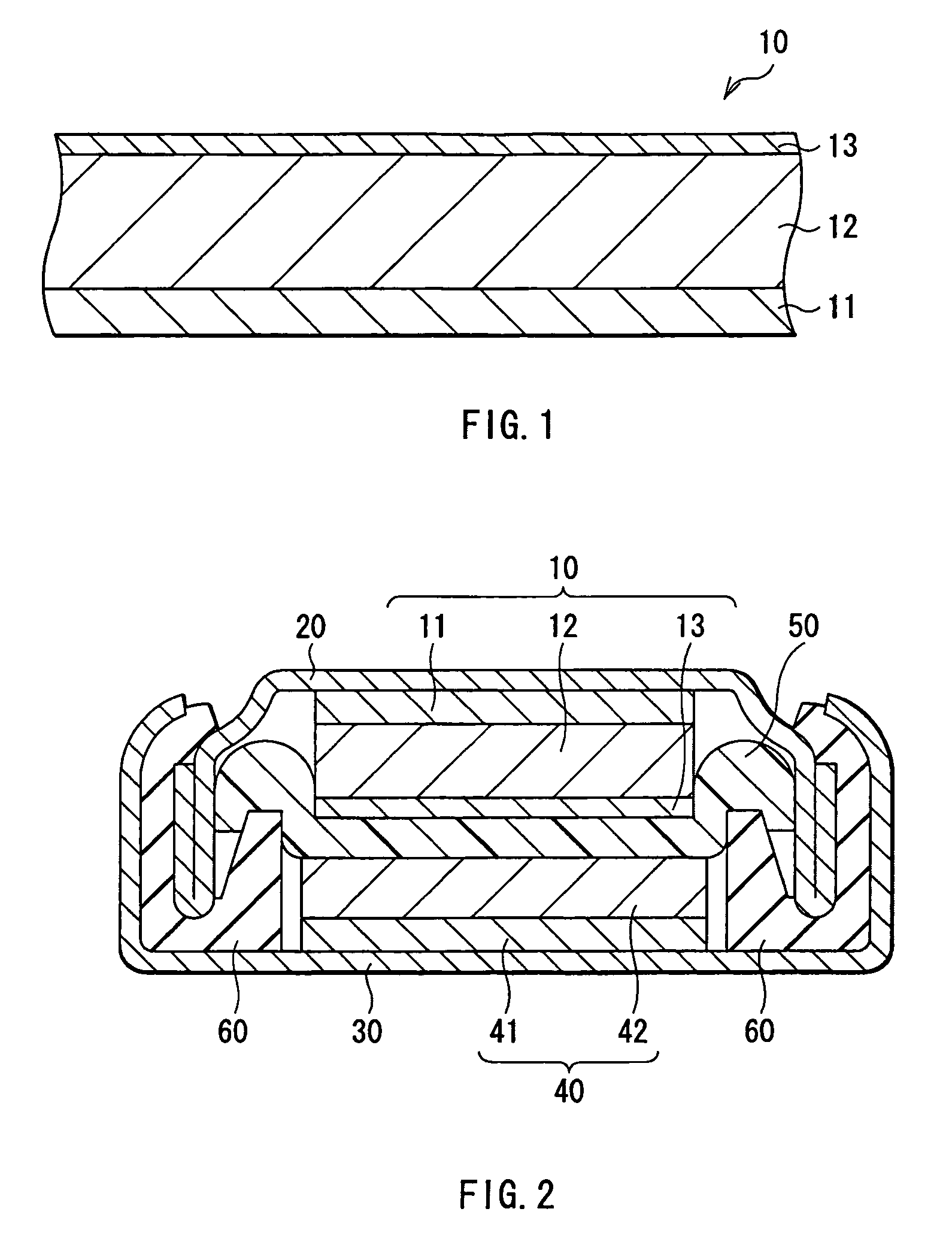
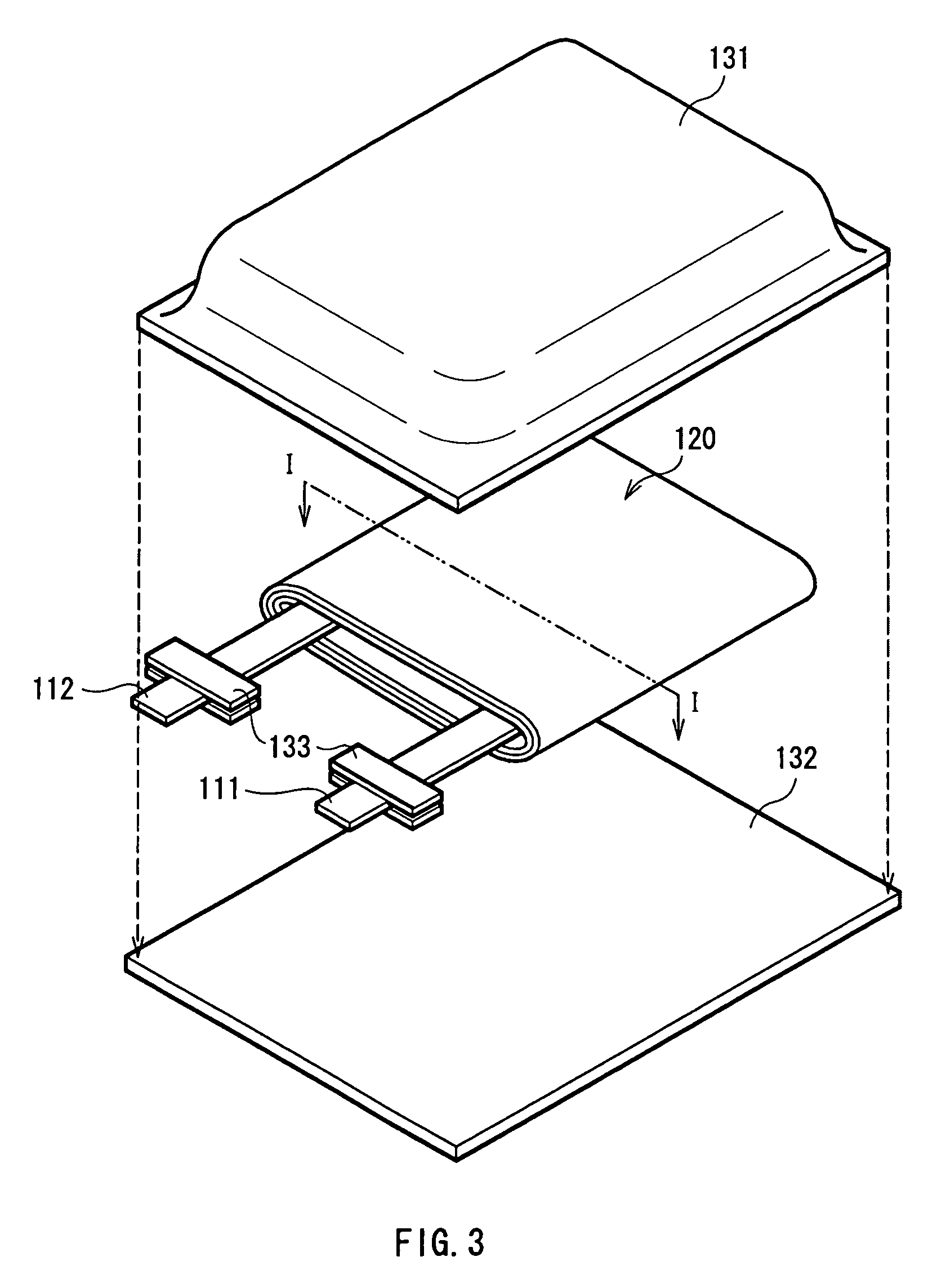
[0075]Secondary batteries shown in FIGS. 3 and 4 were formed. At first, the anode active material layer 12 made of silicon was formed on the anode current collector 11 made of copper foil with a thickness of 15 μm by a sputtering method. Next, lithium metal was deposited on the anode active material layer 12 by a vacuum deposition method. An atmosphere at the time of depositing lithium metal was less than 1×10⁻³ Pa, and the deposition speed was 5 nm / s to 10 nm / s. The amount of deposited lithium metal, that is, the amount of lithium inserted into the anode active material layer 12 in advance was 5% of the anode capacity.

[0076]After lithium metal was deposited, an inactivated gas which included a mixture of carbon dioxide and argon at a volume ratio of 20:80 was introduced into a vacuum chamber at a flow rate of 50 cm3 / min (1 atm, 25° C.), and then a process of inactivating the anode active material layer 12 was carried out. After that, an argon gas was introduced into the vacuum cham...

examples 2-1 through 2-5 , 3-1 through 3-5 , 4-1 through 4-5

Examples 2-1 through 2-5, 3-1 through 3-5, 4-1 through 4-5

[0086]Secondary batteries of Examples 2-1 through 2-5, 3-1 through 3-5 and 4-1 through 4-5 were formed as in the case of Examples 1-1 through 1-5, except that the amount of lithium inserted into the anode active material layer 12 in advance was changed to 10%, 20% and 30%. Moreover, as Comparative Examples 2-1 through 2-5, 3-1 through 3-5 and 4-1 through 4-5, secondary batteries were formed as in the case of Examples 2-1 through 2-5, 3-1 through 3-5 and 4-1 through 4-5, except that no inactivation process by an inactivated gas was carried out. A charge-discharge test was carried out on the secondary batteries of Examples 2-1 through 2-5, 3-1 through 3-5 and 4-1 through 4-5 and Comparative Examples 2-1 through 2-5, 3-1 through 3-5 and 4-1 through 4-5 as in the case of Examples 1-1 through 1-5 to determine their capacity retention ratio in the 50th cycle and measure the degree of the variations by the standard deviation. The ob...


PUM

PropertyMeasurementUnit
thicknessaaaaaaaaaa
flow rateaaaaaaaaaa
diameteraaaaaaaaaa

Abstract

Provided are an anode capable of preventing an increase in impedance and variations in characteristics and a battery using the anode. An anode active material layer includes at least one kind selected from the group consisting of simple substances, alloys and compounds of silicon and the like capable of forming an alloy with Li. The anode active material layer is formed by a vapor-phase deposition method or the like, and is alloyed with an anode current collector. A coating including lithium carbonate is formed on at least a part of a surface of the anode current collector. Thereby, an increase in impedance can be prevented. Moreover, the anode is less subject to an influence by a difference in a handling environment or storage conditions, so variations in impedance can be prevented.

Description

RELATED APPLICATION DATA[0001]The present application claims priority to Japanese Application(s) No(s). P2004-019795 filed Jan. 28, 2004, which application(s) is / are incorporated herein by reference to the extent permitted by law.BACKGROUND OF THE INVENTION[0002]1. Field of the Invention[0003]The present invention relates to an anode comprising an anode current collector and an anode active material layer, and a battery using the anode.[0004]2. Description of the Related Art[0005]In recent years, as mobile devices have higher performance and more functions, higher capacities of secondary batteries as power sources of the mobile devices have been desired. As a secondary battery which meets the requirement, a lithium secondary battery is cited. However, the battery capacity of a currently typical lithium secondary battery which uses lithium cobalt oxide as a cathode and graphite as an anode has reached a point of saturation, so it is extremely difficult to substantially increase the c...

Claims


Application Information

Patent Timeline
Patent Type & Authority Patents(United States)
IPC IPC(8): H01M4/04H01M4/134H01M10/052H01M4/36H01M4/58H01M4/62H01M10/04H01M2/02H01M4/38H01M4/1395H01M4/66H01M4/02H01M10/44H01M4/13H01M4/131H01M4/136H01M4/139H01M4/1391H01M4/1397H01M10/05
CPCH01M2/0222H01M4/134H01M4/1395H01M4/36H01M4/366H01M4/38H01M4/58H01M4/62H01M4/667H01M10/0431H01M10/0436H01M10/052H01M4/0404H01M4/0471H01M4/66H01M10/446H01M2004/027H01M2300/0085Y02E60/122H01M4/386H01M4/387Y02E60/10H01M50/109Y02P70/50H01M4/136H01M10/0525
Inventor KONISHIIKE, ISAMUYAMAMOTO, KENSUKETAKADA, TOMOOIIJIMA, YUKIKOKAWASE, KENICHIMIYAKI, YUKIO
Owner MURATA MFG CO LTD
Why Eureka
Try Eureka