However, if
system control or power is lost, such valves may fail in their current operational mode (i.e., open or closed), thereby enabling continued operation at the current setting.
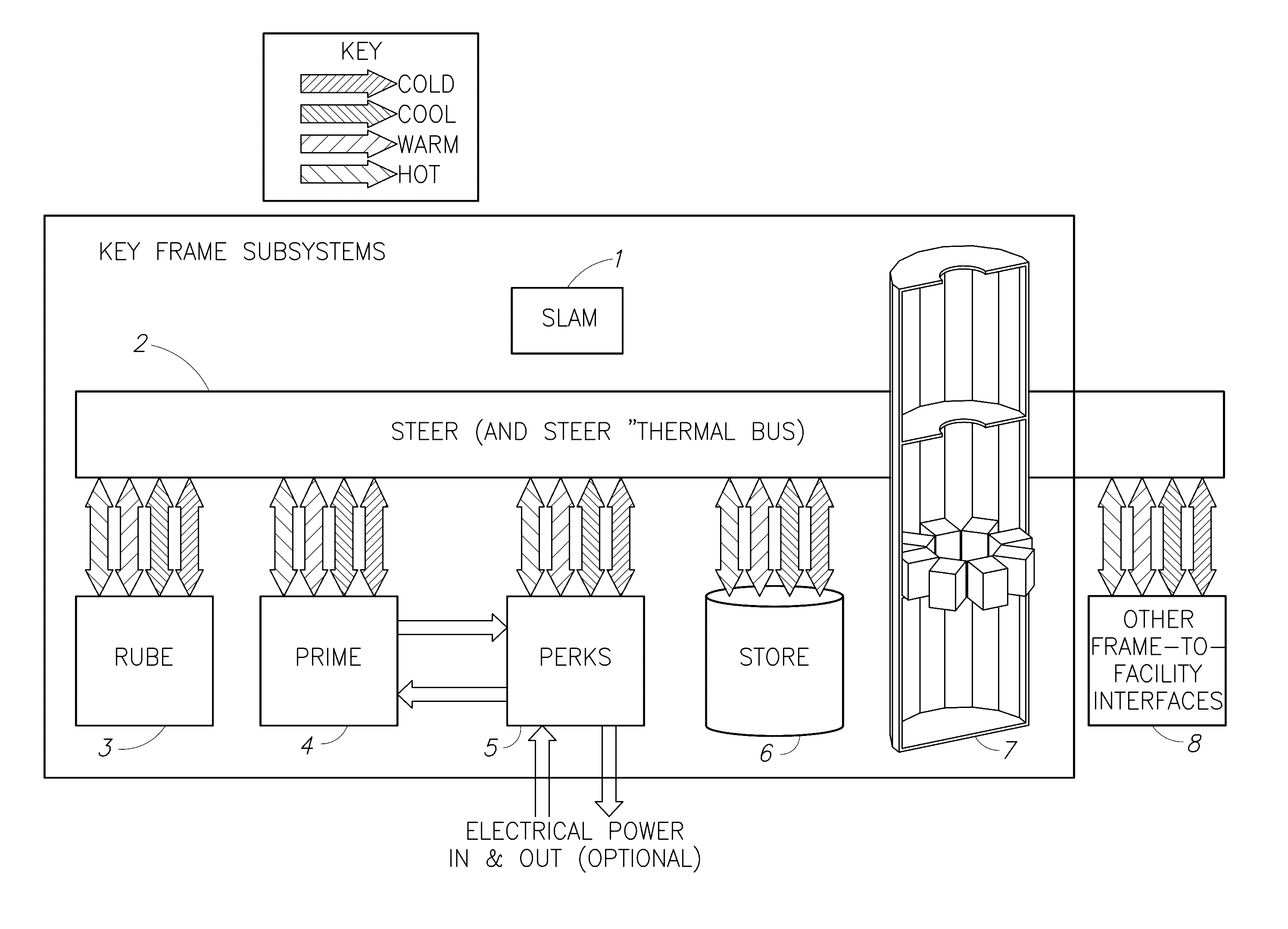
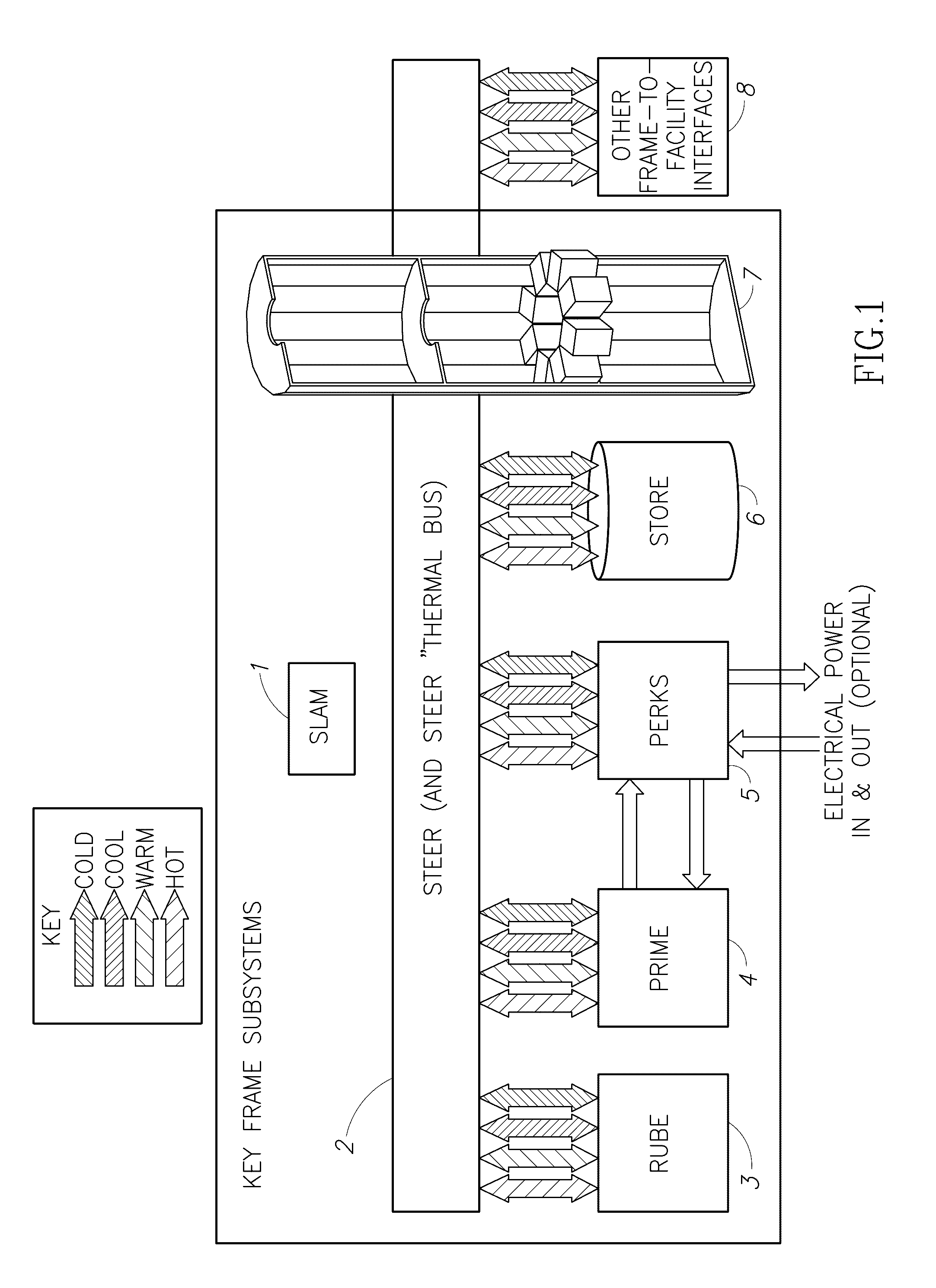
NOTE: By trading four half-couplers for one half-coupler on the FRU side, the FRU may lose flexibility in which thermal channels it may physically connect with.
Depending on the actual implementation, this may be a moot point.
This may be a predominant
data center problem that is partly masked by the fairly rapid equipment turnover (mostly servers) often performed in the name of technology advancement (combined with convenient replacement of “flakey” equipment).
Bad News for High-Heat Servers: CPU Throttling Due to Hidden Thermal Problems
This may be short-sighted because, besides negatively impacting
server reliability, heat can also have a serious, yet hidden,
impact on both
server performance and on energy requirements (energy being the power required over a period of time).
As temperatures increase, transistors get “leaky” (i.e., electrons leak like water) and more power is required, which further increases the temperature and creates a need for additional cooling, which requires still more power.
Such self-preservation efforts consequently also
throttle the CPU performance.
Memory subsystems (e.g., dual-inline memory modules, or DIMMs) are also heat-sensitive and may suffer from heat-induced transient
data loss (flakey operation) or outright hardware failures.
Of course, if a CPU's memory channels slow down, its performance and
throughput must decrease also.
Higher temperatures mean more power is wasted as heat, which also requires additional cooling, and which may contribute to higher local temperatures (e.g., within a
server) that force CPUs and memory to
throttle anyway.
Although one might not observe an immediate decrease in reliability due to increasing the temperature setpoints in a
data center (e.g., to save energy at the
data center level), there will likely be an observed decrease in
throughput across the data center, unless mitigating measures are taken (and effective).
Similar effects may also be observed with unintentional events too, such as dusty heat exchangers, failing fans or blowers, unequal pressurization, or otherwise
restricted airflow.
It may virtually unknown, however, just how large a role the actual processor temperature plays in controlling the amount of power required.
Conversely, however, if the CPU temperature goes down, so may the power dissipation, regardless of the
processing load.
This little-known phenomenon has been documented in manufacturer-provided thermal data for various CPUs, but such data may not be generally available.
Whereas current thinking in the state of the practice is that even an idle processor typically consumes 50% to 60% of its maximum power, FIG. 48 and FIG. 49 strongly suggest that such thinking may be significantly flawed, since the power dissipation (including that of an idle processor) is at least partly a direct function of its case temperature, which in this figure is the only independent variable.
The key problem is that the temperature profile imposed on the processor (e.g., ambient cooling air) will drive the processor's power dissipation to fairly large extent, regardless of what the processor is actually doing (e.g., even if it is idling).
In this example, if the ambient environment is anywhere near 67° C., the processor will barely be
processing, even with a very high
workload.
In other words, the current “leaks” electrons more easily due to smaller physical distances, so this effect gets worse as the industry progresses toward smaller device geometries.
Static current leakage causes power (“static power”) to be consumed even when the FPGAs are not performing tasks (which may be somewhat equivalent to a CPU idling).
In particular, the source-to-drain leakage component of the
total current leakage increases exponentially with increasing temperature, whereas the gate leakage increases more slowly with increasing temperature.
Although FIG. 49 reveals some very bad news for high-heat server environments that may cause processors to exceed the TCASE temperature corresponding to the TDP, thereby inducing throttling, it also reveals very good news for well-cooled server environments.
Rather, the limits are likely to be related to the underlying capabilities of various components to operate together above specific frequencies, possibly due to non-obvious constraints such as available
clock multipliers,
transistor switching speeds,
signal integrity, and mismatched components or configuration settings.
However, the types of systems achieving these speed-ups tend to be poorly suited to data center use (especially on the higher end of the speed-up range), and are generally not intended for long-term unattended operation.
Rather, as with traditional
overclocking, the limits are likely to be related to the underlying capabilities of various components to operate together above specific frequencies (including the CPU cores themselves), possibly due to non-obvious constraints such as available
clock multipliers,
transistor switching speeds,
signal integrity, and mismatched components or configuration settings.
However, increasing a processor's
clock frequency (thereby attempting to accomplish more operations per second) consequently increases the amount of power it consumes, and thus also increases the power it must dissipate.
In general, data centers do not overclock processors because doing so may be fraught with problems, many of which may be directly related to increased heat and the need for additional cooling and power (which may already be acute problems at many data centers).
With just 15%
overclocking, processor “A” ceases to be reliable before even the 36° C. line is reached, suggesting that there may be little possibility of successful
overclocking with data center servers and conventional
air cooling, unless specific processor models are carefully selected, perhaps with processors individually qualified and binned, and possibly not even then.
Furthermore, it is well understood that both the power efficiency and reliability of many electronic devices may degrade with increased
operating temperature, and degradation may often be non-linear.
Temperature-induced throttling is typically a hidden source of performance degradation, which may be severe, and may be a common outcome of misguided efforts to reduce energy costs through suboptimal cooling
system redesign or adjustments to cooling systems (such as raising
chiller set points).
When a PCB reaches saturation temperature, it may be unable to effectively conduct heat away from the
active devices for which it is a substrate.
Even for electronic devices whose
power consumption is not significantly a function of temperature, it may be well understood that both the power efficiency and reliability of many such devices may degrade with increased operating temperature, possibly with non-linear degradation and temperature-induced throttling.
Simply decreasing the temperature of the
working fluid (say, by simply chilling it) can lower the temperature of the devices being cooled, such as CPUs, but may not do so uniformly, or stably, or cost effectively.
The problem is that lowering the temperature of liquid-phase
working fluid by chilling alone may have little effect on
system operating pressure or
boiling point.
Different devices may encounter
working fluid of different temperatures (i.e., heat exchange is not isothermal), and relatively hot devices may cause relatively larger temperature changes to the working fluid.
Thus, subsystems comprising circuit boards further comprising various power-dissipating devices may all be exposed to thermal gradients, meaning that a system may experience not only thermal gradients, but also thermally induced mechanical stresses, even at the
chip level (i.e., different locations on a single device may also experience such thermal gradients, and any induced stresses).
In contrast, open-bath immersion, which must operate essentially at
ambient pressure, cannot—by definition—reduce or increase the operating pressure, and thus cannot dynamically control the
boiling point of the working fluid.
However, efficiently rejecting to ambient may be a short-sighted goal (see next subsection), and operating at such high temperatures sacrifices the power savings and reliability enhancement possible by operating SOI-technology-based devices (such as CPUs) at much lower temperatures (see FIG. 48 and FIG. 50), and also requires high-priced premium chips rated for high temperatures.
First, the devices to be cooled, especially CPUs, tend to operate at the high end of their temperature range, where they may consume the most power.
While the open-bath immersion cooling approach requires only electrical pumping energy (which may be relatively modest compared to power-
hogging vapor compression as used in
refrigeration) to transfer energy away from the bath via a liquid-to-liquid (e.g., phase-change-fluid to cooling water)
heat exchanger, more energy must be removed due to the increased power dissipation of the devices being cooled.
, the water may have very limited opportunities for reuse, especially within a data center environment (it may be used for building heating or
snow melt in the winter, for example, or heating a swimming
pool). H
owever, the hot water may very easily be used to efficiently reject heat directly to the environment, due to the relatively higher-than-ambient temperature, but, in the context of this document, doing so should be recognized as a sheer waste of exergy.
In such a system, the thermodynamic behavior may emulate “semi-open” or “semi-closed” bath systems, but, depending on the actual design, the system may not enjoy the easy-human-access
advantage of a “chest freezer” style design.
Depending on the selected working fluid, this temperature may not be ideal (e.g., in terms of performance, reliability, efficiency, etc.) for many (or any) of the devices to be cooled.
Achieving isothermal operation with separate isothermal operating temperatures for different thermal classes of devices (while operating at
ambient pressure) would call for segregating the devices into different baths with different phase-change working fluids (i.e., having different boiling points at
ambient pressure), which may not be cost-effective, or even feasible.
Note that such embedded condensers or other heat exchangers may add weight and occupy volume that may reduce the functional density of a
modular unit [3.1].
To the extent that embedded condensers or other heat exchangers negatively
impact electrical efficiency, reduced functional density may also comprise reduced performance in terms such as TFLOPS / KW or GFLOPS /
watt., and may also negatively
impact power usage effectiveness, or PUE.
Also, deionized water may be sufficiently
dielectric to be used in carefully controlled circumstances, but if contaminated, it may lose its
dielectric properties and cause short circuits, so we will not discuss it further as a candidate immersion working fluid.
Some concerns include:Oils are messy; immersed circuit boards are wet and oily upon removal, which is undesirableOils have much higher
viscosity, and therefore require more energy for pumping, which is undesirableThe cooler that devices need to be, the higher the
viscosity gets, which is undesirable (
wrong direction)Oils operate without phase-change, and thus acquire only
sensible heat, not
latent heat (loss of 10×
advantage)Oils do not operate at
boiling point, and thus cannot operate isothermally (
high heat fluxes may induce thermal stress)Oils cannot avoid temperature glide (thermal gradients), although faster pumped flows may help (takes more energy)At electronic device temperatures, heat is relatively difficult to acquire (and even harder to reject, especially to air)
However, note that, unlike the usual or conventional construction of TEC-device-based assemblies, a preferred embodiment may not use compression on the primary surfaces of the TEC devices for device retention or to create a thermal interface of low
thermal resistance.
In other words, the built-in redundancy allows the same work to be accomplished without changing the level of committed operational flows, but less efficiently from an electrical power efficiency viewpoint (or alternatively, to maintain the same COP, less work may need to be done, or the committed operational flows may need to be reduced).
Thus, the traditional COP calculation may be misleading, because the system effectively may operate at much higher efficiencies than a simple COP calculation would indicate (not unlike a combined heat and power, or CHP, system).
This may cause heating and / or thawing to occur in Chamber 1, and also may cause pre-cooling to occur in Chamber 2.
The parameters that affect efficient thermochemical adsorption are also greatly affected by thermal issues, not the least of which is that, since adsorption is an
exothermic reaction that is temperature-limited, the failure to efficiently remove heat may prevent or terminate the very reaction sought, and the reverse is true for
desorption.
In general, junction temperatures greater than those specified for reliability (e.g., stress ratings) may cause permanent damage, and device functional operation at or above such conditions is not implied.

